Frameless Inrunner Torque Motors with Custom Rotor and Shell
Introduction
Motor sizing is a critical step in ensuring optimal performance, efficiency, and longevity of motors in various applications. Selecting the right motor—especially for torque motors—affects speed, load handling, and overall system reliability. Incorrect motor sizing can lead to overheating, excessive power consumption, or mechanical failures.
To size a motor correctly, key factors such as torque requirements, speed, inertia matching, and dty cycle must be considered. Industries like robotics, industrial automation, aerospace, and medical equipment all rely on precise motor selection for seamless operation.
Mosrac provides cutting-edge solutions to meet diverse requirements, helping industries make informed choices between motors, based on their unique applications!
Understanding Motor Sizing Basics
Motor sizing is the process of selecting the appropriate motor based on the specific requirements of an application, ensuring optimal performance, efficiency, and longevity.
This involves calculating torque, speed, power, inertia, and other critical parameters to match the capabilities of a motor with system demands.
1. Types of Motors in Motor Sizing
Selecting the right motor depends on the specific needs of the applications. Here’s an overview of the most common types of motors used in industrial and automation systems:
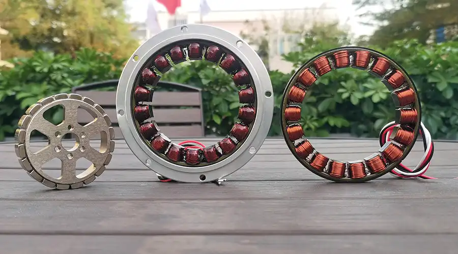
A: Torque Motors
Torque motors are designed to provide continuous torque at low speeds without overheating. These motors are commonly used in direct drive applications where high precision and smooth motion control are required.
Torque Motor
The key features include:
▪︎ High torque at low speeds
▪︎ No need for gear reduction
▪︎ Ideal for robotics, CNC machines, and indexing tables
The rated torque of the motor is calculated with the following equation:
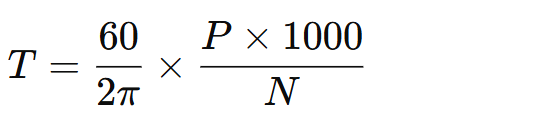
where, T = Torque (Nm), P = Power (kW), and N = Rotational speed (RPM)
B: Stepper Motors
Stepper motors operate in discrete steps, making them ideal for applications requiring precise positioning and repeatability. They are often used in automation, 3D printing, and medical devices.

Stepper Motor
The key features include:
▪︎ High positional accuracy
▪︎ No need for feedback systems
▪︎ Works well for low-speed, high-precision tasks
The formula for Step Angle (θ) is:

where, θ = Step angle per pulse, and Ns= Number of steps per revolution
C: Servo Motors
Servo motors provide closed-loop control, ensuring accurate speed and position control. They are widely used in industrial automation, robotics, and motion control systems.
Industrial Servo Motor
The key features include:
▪︎ High efficiency with precise feedback control
▪︎ Smooth motion with a high torque-to-weight ratio
▪︎ Excellent for dynamic load applications
The formula for speed control in servo motors:
where, N = Motor speed (RPM), V = Applied voltage, p = Number of poles, and Φ = Magnetic flux per pole
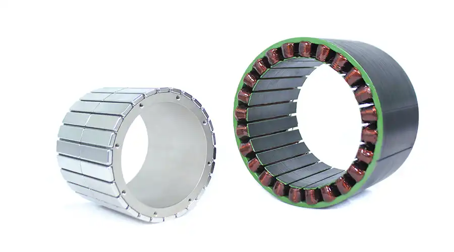
D: Brushless DC (BLDC) Motors
BLDC motors offer high efficiency and durability due to the absence of brushes, reducing wear and tear. These motors are widely used in drones, electric vehicles, and industrial fans.
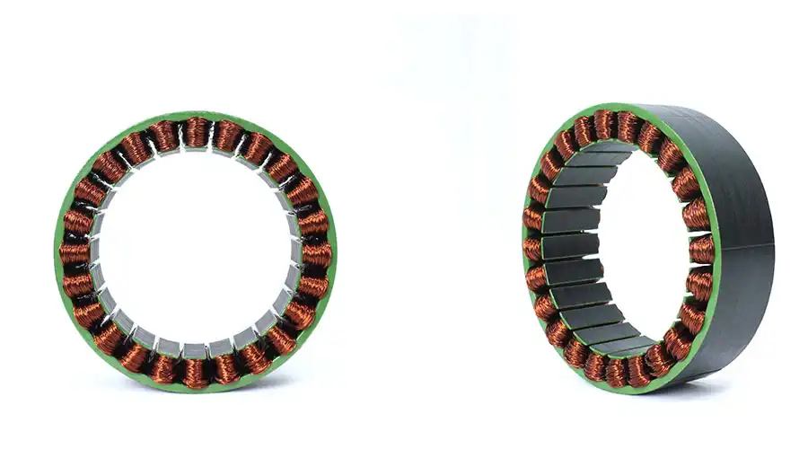
Brushless DC Motors
The key features include:
▪︎ High power density and efficiency
▪︎ Longer lifespan with minimal maintenance
▪︎ Suitable for variable-speed applications
The formula for Power in BLDC motors is:
where, P = Power output (W), V = Voltage (V), I = Current (A), and η = Efficiency (%)
Recommended Reading: Frameless Motor VS Brushless Motor: Which is Right for You?
2. Key Factors Affecting Motor Selection
When performing motor sizing, engineers must consider various factors to ensure the selected motor meets performance and operational requirements.
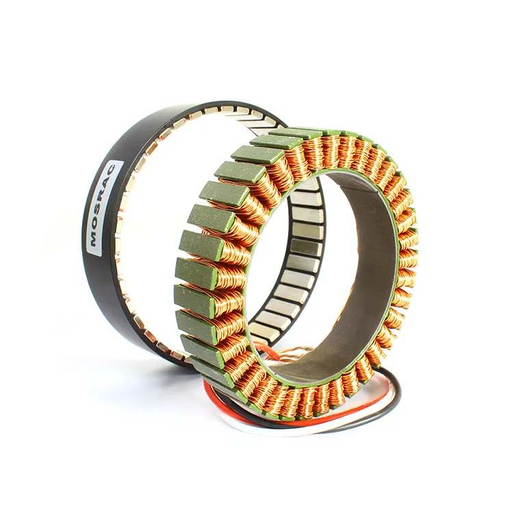
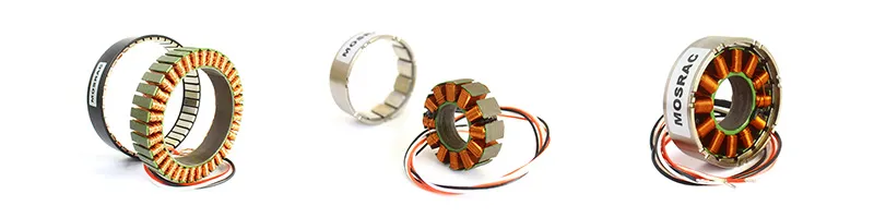
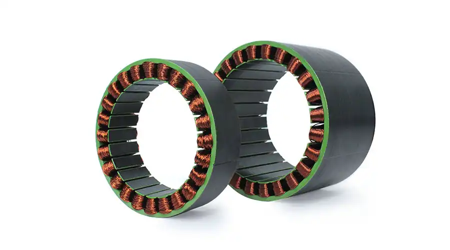
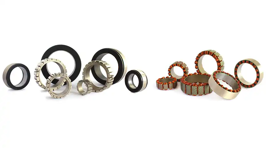
Rotor and Stator detail of an electric motor
A: Torque Requirements
▪︎ Continuous Torque: The constant torque the motor must provide.
▪︎ Peak Torque: The highest torque needed during acceleration or sudden load changes.
▪︎ Holding Torque (for stepper motors): The torque required to maintain a stationary position.
The formula for Torque calculation is:
where, T = Torque (Nm), F = Force (N), and r = Radius (m)
B: Speed and Power Requirements
▪︎ The speed of the motor is determined by the required operational cycles per second.
▪︎ The power rating must align with the system’s energy demand to avoid inefficiencies.
The formula for Power calculation is:
where, P = Power (W), T = Torque (Nm), and ω = Angular velocity (rad/s)
C: Inertia Matching
▪︎ The inertia of the motor should be appropriately matched with the load inertia to ensure smooth motion and prevent mechanical stress.
▪︎ High inertia mismatch can cause instability and inefficient operation.
The formula for Inertia Ratio is:

where, R = Inertia Ratio, JL= Load inertia (kg.m²), and JM= Motor inertia (kg.m²)
D: Duty Cycle Consideration
▪︎ Determines how long the motor will operate under full load conditions.
▪︎ Motors with high duty cycles require better thermal management to prevent overheating.
The formula for the Duty Cycle is:
where, ton = Motor operating time, toff = Motor resting time
Recommended Reading: What is a BLDC Motor? A Comprehensive Guide to Brushless DC Motors
Key Motor Sizing Parameters
Selecting the right motor for an application requires a detailed understanding of critical parameters that impact performance, efficiency, and reliability.

Copper Coil Winding + Sizing in an electric motor
Motor sizing involves analyzing torque, speed, power, inertia, acceleration, duty cycle, and thermal considerations to ensure the motor meets system requirements without excessive wear or inefficiency.
1: Torque Requirements
Torque is the rotational force exerted by a motor and is a primary factor in motor sizing. There are three key types of torque that must be considered:
A: Continuous Torque (Tcont)
Continuous torque is the steady-state torque required to keep a system operating under normal load conditions. This is the torque the motor must provide continuously without overheating.
The formula for Continuous Torque is:
where, Tcont = Continuous Torque (Nm), F = Force applied (N), r = Radius of rotation (m), η = System efficiency (decimal)
B: Peak Torque (Tpeak)
Peak torque is the maximum torque required during acceleration, deceleration, or load spikes. Motors must be selected with enough margin to handle peak loads without stalling.
The formula for Peak Torque is:

where, Tpeak = Peak Torque (Nm), J = Rotational inertia (kg·m²), and α = Angular acceleration (rad/s²)
C: Holding Torque (Tholding) – For Stepper Motors
Holding torque is the torque required to keep a motor in position without movement when no external force is applied. It is essential in positioning applications such as robotics and CNC machines.
The formula for Holding Torque is:
where, Tholding = Holding torque (Nm), I = Motor current (A), KT= Motor torque constant (Nm/A)
2: Speed and Power Considerations
Speed and power determine how effectively a motor can perform within an application. The relationship between motor speed (RPM), torque, and power plays a crucial role in selecting the right motor.
A: Determining the Optimal Motor Speed (RPM)
Speed is dictated by the required motion profile of the system. Choosing the correct RPM ensures proper synchronization between the motor and the load.
The formula for Motor Speed (N) is:
where, N = Motor speed (RPM), f = Supply frequency (Hz), and P = Number of poles in the motor
B: Relationship Between Speed, Torque, and Power
The mechanical power output of a motor is directly related to torque and speed.
The formula for Power (P) is:

where, P = Power (W), T = Torque (Nm), and ω = Angular velocity (rad/s)
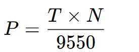
or in RPM form:

where, T = Torque (Nm), P = Power (kW), and N = Rotational speed (RPM)
Higher speeds require higher power, but torque drops as speed increases in constant-power motors.
3. Load Inertia & System Inertia Matching
Inertia is a crucial factor in motor selection, as improper load-to-motor inertia matching can lead to instability, inefficiency, and excessive wear on the motor.
A: Importance of Load-to-Motor Inertia Ratio
For optimal motion control, the motor inertia should not exceed 10 times the load inertia. A 1:1 to 5:1 ratio is typically preferred in high-precision applications.
The formula for Inertia Ratio is:
where, R = Inertia Ratio, JL= Load inertia (kg.m²), and JM= Motor inertia (kg.m²)
Rule of Thumb: If R > 10, consider using gear reduction to balance the system.
B: Methods to Reduce Excessive Inertia Mismatch
1. Use a Gearbox: Reduces the effective inertia seen by the motor.
2. Choose a Motor with Lower Rotor Inertia: Optimizes performance.
3. Increase the Load Inertia (if practical): Improves balance in some applications.
The formula for Adjusted Load Inertia (JLeff) with Gear Reduction:
where, JLeff = Effective load inertia, JL= Original load inertia, and r = Gear ratio
4: Duty Cycle and Thermal Considerations
The duty cycle of the motor determines how long it operates under load conditions before cooling down. Higher duty cycles require better thermal management.
Understanding Duty Cycle (%)
The formula for the Duty Cycle is:

where, ton = Motor operating time, toff = Motor resting time
Examples:
▪︎ 100% Duty Cycle (Continuous operation): Requires high-efficiency motors with advanced cooling.
▪︎ 50% Duty Cycle: The motor runs half the time, reducing thermal buildup.
Managing Thermal Load and Heat Dissipation
▪︎ Use Active Cooling: Fans or liquid cooling for high-performance applications.
▪︎ Increase Motor Efficiency: Select motors with lower losses.
▪︎ Monitor Temperature: Use sensors for real-time feedback.
The formula for Motor Heat Generation (Q):
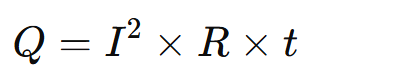
where, Q = Heat generated (Joules), I = Current (A), R = Motor winding resistance (Ω), and
t = Time (s)
5: Acceleration and Deceleration Requirements
Acceleration and deceleration define how quickly a motor reaches its desired speed. Incorrect acceleration settings can lead to mechanical stress and inefficient motion profiles.
The formula for Angular Acceleration (α):
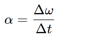
where, α = Angular acceleration (rad/s²), Δω = Change in angular velocity (rad/s), Δt = Time taken (s)
Here, the faster acceleration is equal to the higher torque demand.
Step-by-Step Motor Sizing Calculation
The motor sizing starts with a first-pass estimation of all loading and a simple move profile defining the worst-case acceleration and velocity requirements. This process follows the Laws of Motion by Newton.
1. Define/calculate the key aspects of the motion profile required.
2. Calculate/estimate all of the torque loadings in the system.
3. Estimate any additional torque required due to the environment or the system dynamics.
4. Check your results against an initial motor selection that fits within your desired size and physical constraints.
5. Factor in the motor itself to the system and repeat step 4 if necessary.
6. Check the electrical input power requirements to see that they align with what’s available.
For successful motor sizing, three important factors must be determined: torque, inertia, and speed.
Recommended Reading: How to Choose the Right Torque Motor: 14 Essential Criteria
Application Considerations
Choosing the right motor involves more than just torque and speed calculations. Environmental factors, system compatibility, and design flexibility play a significant role in ensuring the motor operates efficiently in real-world applications. This section explores key considerations that impact motor selection.
1. Environmental Factors
The operating environment directly affects motor performance and longevity. Selecting a motor that withstands specific environmental conditions ensures reliability and reduces maintenance costs.
A: Temperature Tolerance
▪︎ Extreme Heat: Motors operating in high temperatures require advanced cooling mechanisms such as forced air or liquid cooling.
▪︎ Cold Environments: Low temperatures can impact motor lubrication and increase mechanical resistance. Specialized low-temperature lubricants and insulation materials are recommended.
Industry Example: In automotive manufacturing, motors used in paint curing applications must withstand high-temperature ovens without thermal degradation.
B: Humidity and Moisture Resistance
▪︎ High-humidity environments can cause corrosion and electrical short circuits.
▪︎ Motors with IP65 or higher ratings are essential for protection against water and dust.
▪︎ Encapsulation or conformal coating can be used for added moisture resistance.
Industry Example: In food processing plants, motors must meet IP67/IP69K ratings to withstand high-pressure washdowns.
C: Shock and Vibration Resistance
▪︎ High-vibration applications (e.g., CNC machines, and aerospace systems) require motors with robust mounting and reinforced bearings to prevent misalignment.
▪︎ Shock load conditions may necessitate torsionally stiff couplings to absorb mechanical impact.
Industry Example: In railway applications, locomotive motors must endure continuous vibration and temperature fluctuations.
2. Integration with Existing Systems
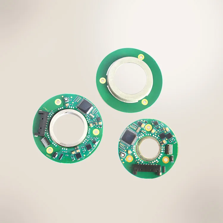
A: Compatibility with Controllers and Encoders
Seamless integration with controllers and feedback systems is critical for precision control in motion applications.
▪︎ Servo Motors: Require high-resolution encoders (absolute or incremental) for closed-loop feedback.
▪︎ Stepper Motors: Work with open-loop or closed-loop drivers, depending on positioning accuracy requirements.
▪︎ Torque Motors: Often paired with magnetic absolute encoders for precise torque control.
Industry Example: In automated robotics, high-speed robotic arms use servo motors with absolute encoders to maintain accuracy in pick-and-place operations.
B: Communication Protocols
Modern industrial motors support various communication interfaces for integration with PLCs and motion controllers:
| Communication Protocol | Application |
| EtherCAT | High-speed motion control (CNC, robotics) |
| PROFIBUS/PROFINET | Industrial automation (conveyors, packaging machines) |
| CANopen | Automotive and medical applications |
| Modbus RTU/TCP | General-purpose motor control |
Best Practice: Select motors pre-configured with compatible communication protocols to simplify integration and reduce system complexity.
3. Custom vs. Standard Solutions
A: When to Choose Standard Motors?
▪︎ Off-the-shelf motors are cost-effective for general applications.
▪︎ Suitable for applications where load, speed, and environmental conditions match standard specifications.
▪︎ Ideal for conveyor belts, cooling fans, and general industrial automation.
Example: In Fan Motors in HVAC Systems, standard BLDC motors are used in ventilation systems due to their availability and efficiency.
B: When to Opt for Custom Motor Designs?
In specialized applications, custom motor solutions are necessary to optimize performance and efficiency.
▪︎ Unique Voltage & Power Requirements – Custom winding designs for optimized performance.
▪︎ Special Mounting & Form Factor – Compact or uniquely shaped motors for space-constrained applications.
▪︎ Extreme Environmental Conditions – Motors with hermetic sealing, specialized coatings, or high-durability materials.
▪︎ Application-Specific Torque & Speed – Custom torque curves for demanding motion profiles.
Example: Medical Imaging (MRI Machines) uses custom torque motors with non-magnetic materials for precise imaging without interference.
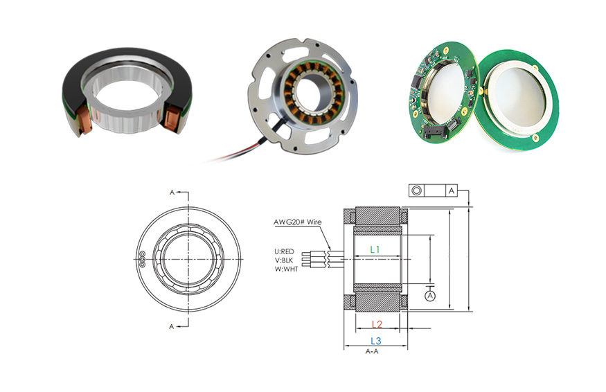
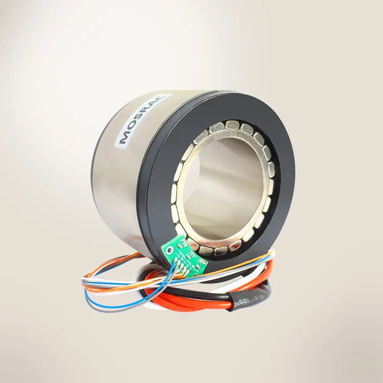
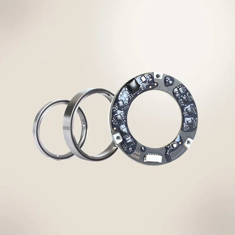
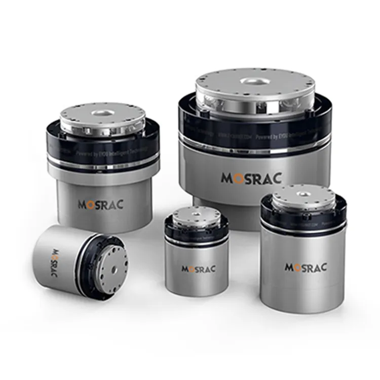
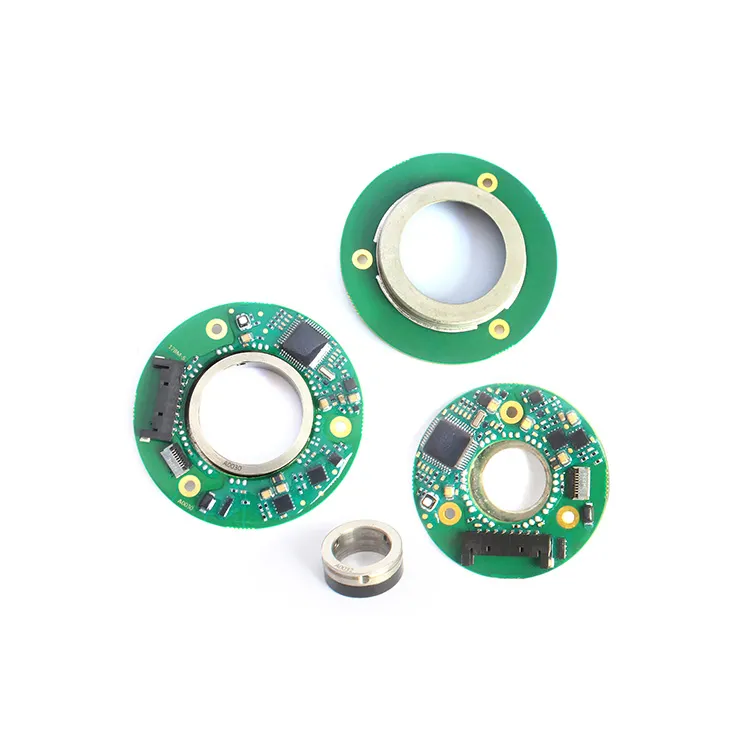
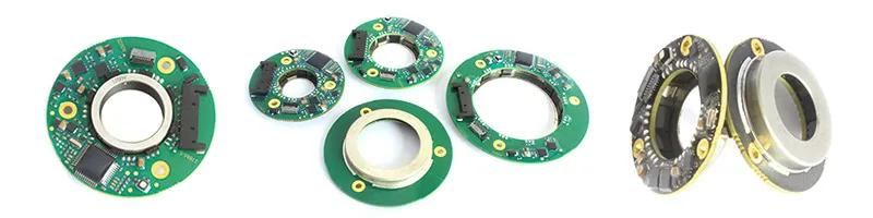
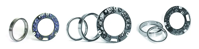
At MOSRAC, we specialize in the design and manufacturing of frameless torque motors and direct drive rotary (DDR) motors, engineered to deliver unmatched torque density, accuracy, and reliability for high-performance applications!
Frameless motors offer unparalleled flexibility, allowing engineers to integrate them directly into customized assemblies while maintaining high torque-to-weight ratios.
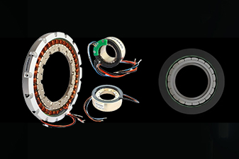
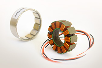
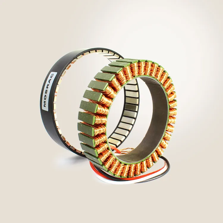
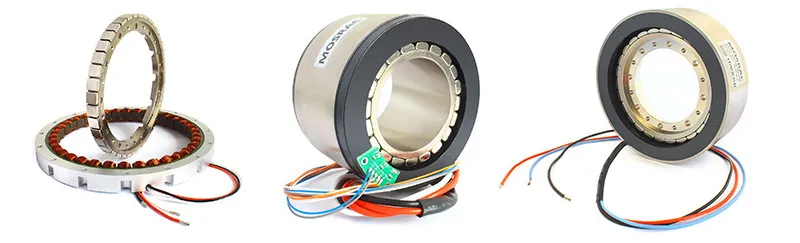
Mosrac Frameless Torque Motors
Key benefits include:
▪︎ Compact Design: No external housing, allowing for customized integration into specialized machinery.
▪︎ High Torque-to-Weight Ratio: Ideal for robotic arms, aerospace actuators, and medical devices.
▪︎ Modular Compatibility: Designed to work with multiple winding configurations for performance optimization.
Direct Drive Rotary (DDR) motors eliminate gear systems, providing:
▪︎ Frictionless, High-Precision Motion: Suitable for robotic applications, industrial automation, and semiconductor manufacturing.
▪︎ Elimination of Mechanical Wear: Extends motor lifespan, reducing maintenance costs.
▪︎ Seamless Integration with Custom Windings: Supports low-cogging, high-efficiency winding solutions.
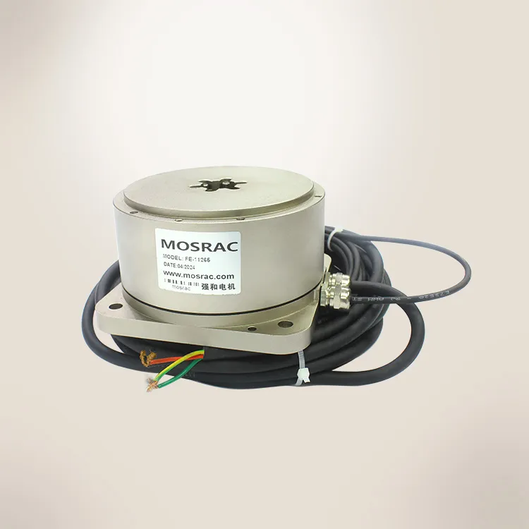
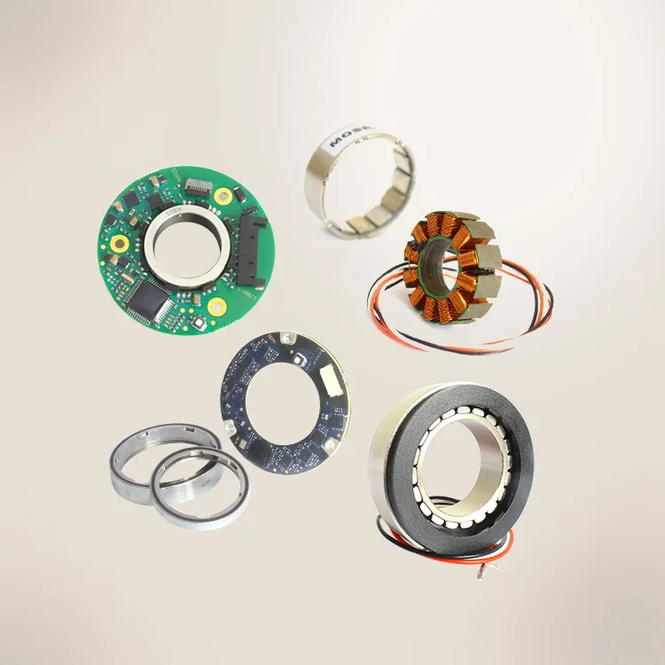
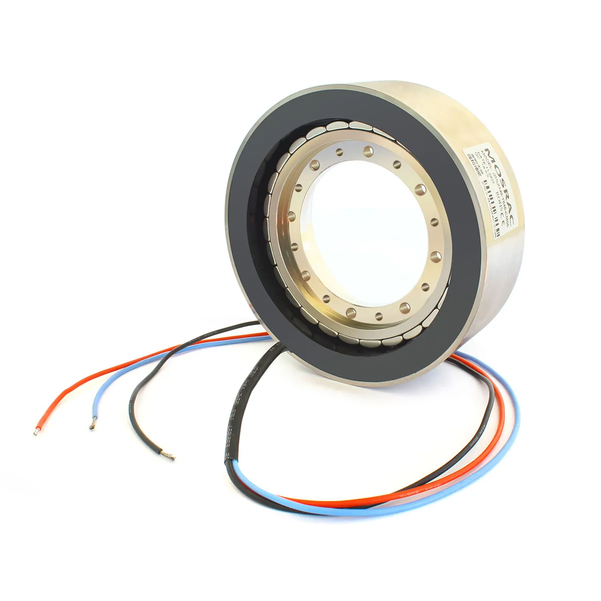
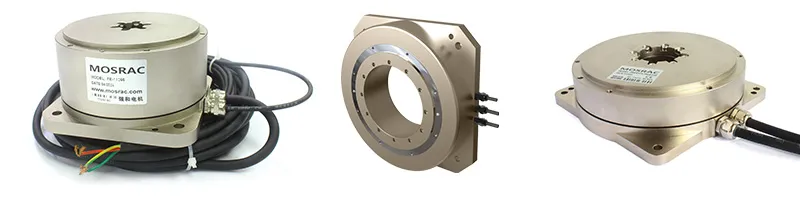
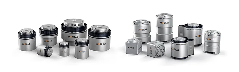
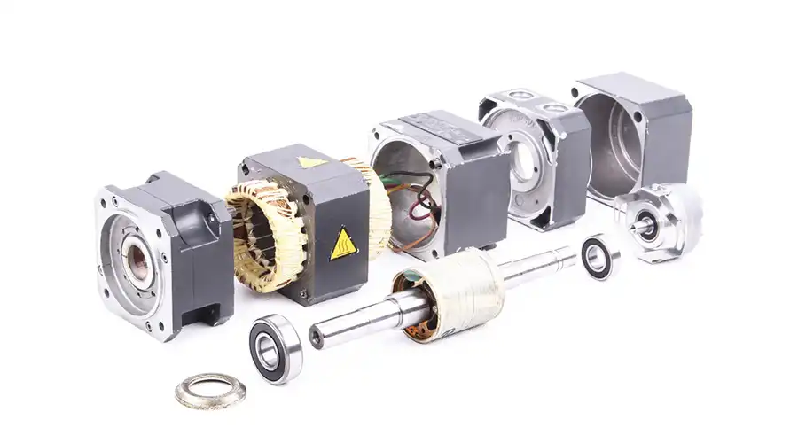
Frameless Torque Motors & Housed Direct Drive Torque Motors (DDR motors)
DDR motors manufactured by Mosrac include the FE series and FI series, with various size options for different application needs, the OD ranges from 40mm to 375mm.
Looking for high-performance, next-generation motor solutions? Contact MOSRACtoday to explore high-torque, high-efficiency motor solutions, or customized motor solutions according to your needs!
Case Study: Selecting a Torque Motor for a Robotics Application
1. Defining Application Requirements
A: Application Overview
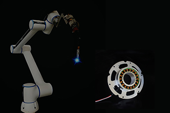
The selected application involves a robotic arm used in an industrial automation setting, requiring precise positioning, high torque, and smooth motion control. The torque motor must handle variable loads, continuous operation, and rapid acceleration/deceleration cycles while maintaining high efficiency and durability.
B: Key Performance Parameters
| Parameter | Specification | Justification |
| Load Torque (Nm) | 25 Nm | Required for lifting and holding payloads |
| Peak Torque (Nm) | 50 Nm | Needed for rapid acceleration phases |
| Speed (RPM) | 2000 RPM | Ensures efficient motion cycles |
| Inertia Ratio | <5:1 | Optimal for stable and responsive motion |
| Duty Cycle (%) | 80% | High utilization in industrial robotics |
| Power Supply | 48V DC | Standard for robotic applications |
| Operating Temperature | -10°C to 60°C | Ensures functionality in factory environments |
2. Step-by-Step Selection Process
Step 1: Torque Calculation
The total torque required consists of load torque, acceleration torque, and frictional losses.
A. Load Torque Calculation
The robotic arm must lift a 5 kg payload at a lever arm length of 0.5 meters. The gravitational force acting on the payload is:
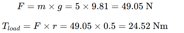
Here, a motor with at least 25 Nm continuous torque is required to support this load!
B. Acceleration Torque Calculation
The robotic arm must reach its maximum speed in 0.2 seconds. The angular acceleration is:

Given a load inertia of 0.015 kg·m², the acceleration torque is:

Here, peak torque must account for acceleration torque, totaling at least 50 Nm!
Step 2: Speed and Power Considerations
The motor must maintain 2000 RPM under load. Using the power equation:
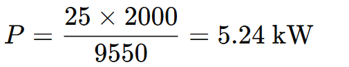
Here, a motor rated at ≥5.5 kW is recommended for sustained operation!
Step 3: Inertia Matching for Stability
To prevent instability, the inertia ratio should be ≤5:1:

Given motor inertia JM = 0.005 kg·m²:
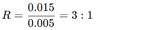
So, this ratio ensures optimal motion control!
Step 4: Motor Selection Based on Performance Criteria
After considering torque, speed, inertia, and power requirements, the selected MOSRAC Frameless Torque Motor must meet:
| Specification | Requirement | Selected Motor |
| Continuous Torque (Nm) | 25 Nm | Required for lifting and holding payloads |
| Peak Torque (Nm) | 50 Nm | Needed for rapid acceleration phases |
| Speed (RPM) | 2000 RPM | Ensures efficient motion cycles |
| Inertia (kg·m²) | <5:1 | Optimal for stable and responsive motion |
| Duty Cycle (%) | 80% | High utilization in industrial robotics |
| Power Supply | 48V DC | Standard for robotic applications |
| Operating Temperature | -10°C to 60°C | Ensures functionality in factory environments |
So, the U Series Frameless Torque Motor by MOSRAC is the optimal choice!
3. Justification of Chosen Motor Specifications
A: High Torque Density & Efficiency
▪︎ The frameless design eliminates unnecessary housing weight, improving efficiency.
▪︎ 30 Nm continuous torque allows reliable operation under load.
▪︎ 60 Nm peak torque ensures smooth acceleration and deceleration.
B: Precision Motion Control
▪︎ Low rotor inertia (0.0045 kg·m²) ensures rapid response times.
▪︎ Supports direct drive configurations, eliminating backlash and improving precision.
C: Seamless System Integration
▪︎ Compatible with standard robotic controllers and encoders.
▪︎ Modular form factor allows customized mounting options.
Recommended Reading: 8 Different Types of Robot Motors: What They Are, Why Use Them, and How to Choose Motor
Conclusion
Proper motor sizing is essential for achieving optimal performance, energy efficiency, and longevity in industrial applications. By carefully evaluating torque, speed, power, and inertia, engineers can select the right motor to prevent overheating, excessive wear, and inefficiencies.
Well-sized motors enhance precision, reduce maintenance costs, and improve overall system reliability. Using professional motor sizing tools and consulting with experts ensures the best-fit solution for robotics, automation, and high-performance applications.
Frequently Asked Questions
1. How do I determine the right motor size for my application?
A. Calculate torque, speed, power, and inertia based on load requirements, duty cycle, and environmental conditions to ensure optimal performance.
2. Why is motor sizing important?
A. Proper motor sizing prevents overheating, reduces energy consumption, improves efficiency, and extends motor lifespan, ensuring reliable performance in industrial applications.
3. What factors influence motor sizing?
A. Key factors include torque, speed, power, load inertia, duty cycle, and environmental conditions to ensure compatibility with application requirements.
Looking for a Custom Solution?
Tell us about your requirements, and our application engineers will help you find the right solution today!