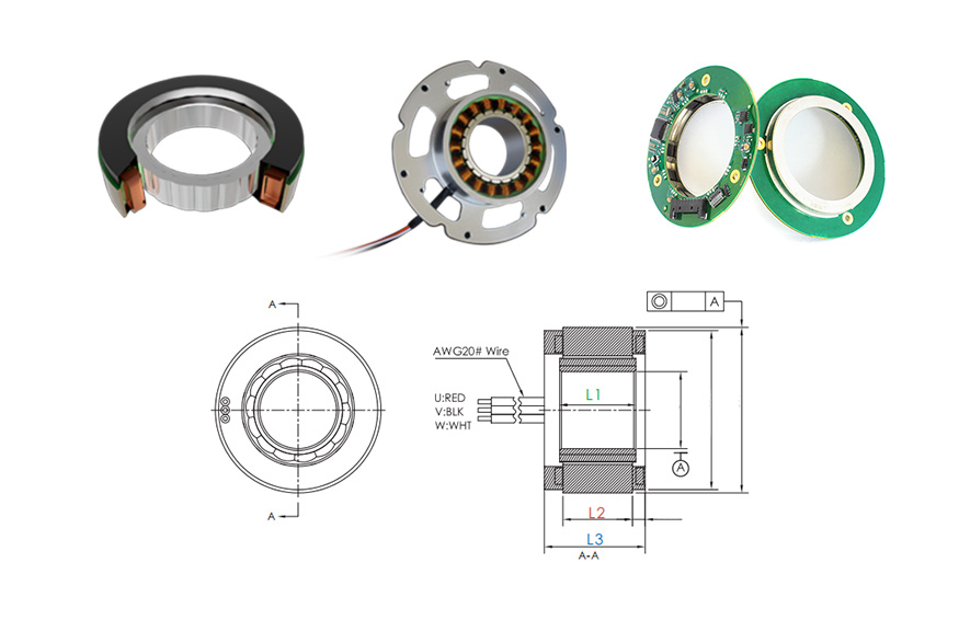
U160 Series Brushless Frameless Inrunner Motor
Introduction
Motor cogging is a common issue in electric motors, particularly in permanent magnet motors, where unwanted jerky motion occurs at low speeds due to magnetic interaction between the rotor magnets and stator slots. This irregular motion, known as motor cogging, can significantly impact the smoothness and efficiency of motor performance.
In high-precision applications such as robotics, CNC machinery, and medical devices, even slight cogging can lead to performance degradation. By understanding the causes and implementing the right design and control strategies, engineers can effectively reduce cogging and ensure optimal motor performance across various applications.
Mosrac provides cutting-edge solutions to meet diverse requirements, helping industries make informed choices between motors, based on their unique applications!
Understanding Cogging Torque
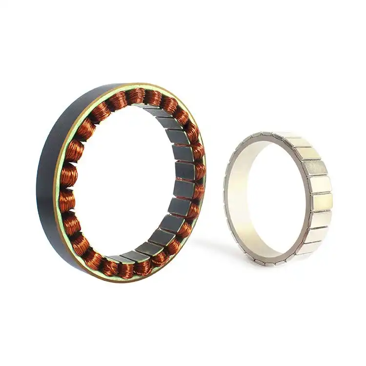
Cogging torque, also known as detent or no-current torque, arises from the interaction between the perma
nent magnets and stator slots of a motor. This phenomenon is particularly prevalent in permanent magnet synchronous motors (PMSMs).
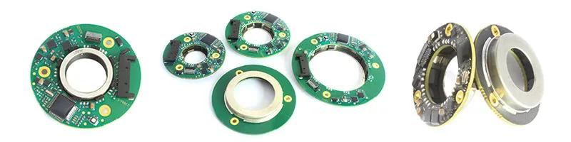
Permanent Magnet Synchronous Motors (PMSMs); Source: about-motors
The magnetic attraction between the magnets of the rotor and the teeth of the stator creates a position-dependent torque that resists smooth rotation. This resistance is especially noticeable when the rotor teeth align with the stator teeth, resulting in a reluctance torque that can cause jerky motion at low speeds.
The presence of cogging torque can significantly affect motor performance:
-
▪︎ Torque Ripple: Variations in torque output, known as torque ripple, can lead to vibrations and acoustic noise, compromising the precision required in applications like robotics and CNC machinery.
-
▪︎ Velocity Ripple: Inconsistent rotational speeds, or velocity ripple, can degrade the quality of processes dependent on uniform motion, such as printing or semiconductor manufacturing.
-
▪︎ Energy Efficiency: Additional losses due to cogging torque necessitate higher energy consumption to maintain desired performance levels, reducing overall system efficiency.
To mitigate cogging torque, various design strategies are employed, such as skewing stator slots or magnets, using fractional slots per pole, and optimizing magnet pole arc or width.
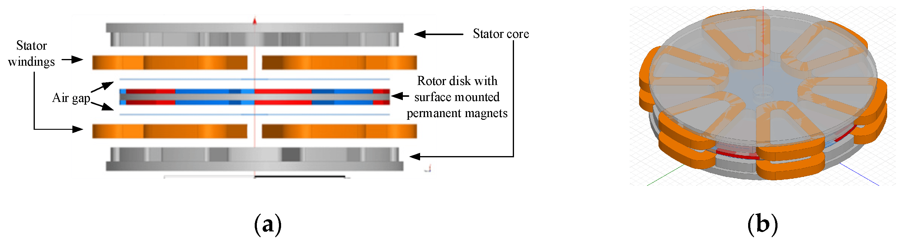
Cogging Torque Reduction Techniques in Axial Flux Permanent Magnet Machines; Source: MDPI
For instance, fractional slot windings can lower cogging torque by minimizing torque pulsations, ensuring smoother motor operation and enhanced efficiency. Implementing these techniques can reduce cogging torque but may also affect other motor characteristics, necessitating a balanced approach.
Recommended Reading: Understanding Motor Windings: Key Differences, Benefits, and Innovations
Distinguishing Between Cogging Torque and Torque Ripple
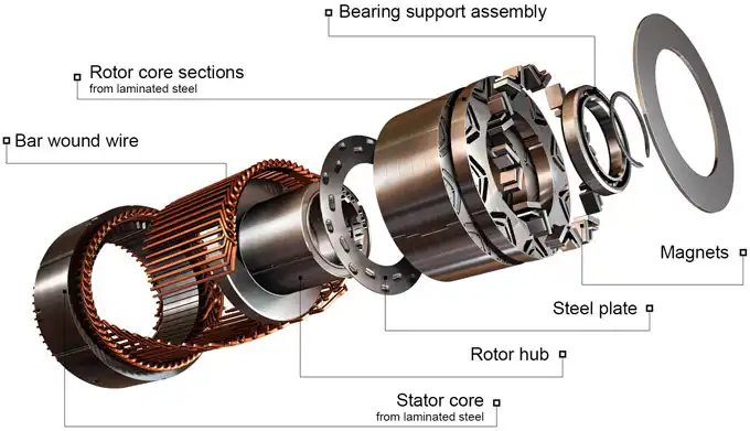
Let’s start with understanding cogging torque! It is a position-dependent torque that occurs in permanent magnet motors when the rotor magnets align with the stator teeth. This interaction creates a reluctance torque that resists rotor motion, particularly at low speeds, even when no current flows. It's a design-related phenomenon influenced by stator slot geometry, magnet alignment, and slot harmonics.
Cogging Torque vs Torque Ripple; Source: kollmorgen
In contrast, torque ripple refers to periodic fluctuations in torque during motor operation under load. Unlike cogging torque, torque ripple is dynamic and influenced by current variations, magnetic saturation, and controller inaccuracies.
Let’s go through their core differences:
| Aspect | Cogging Torque | Torque Ripple |
| Definition | Position dependent torque, caused by magnetic attraction between stator teeth and rotor magnets. | Variations in torque during rotation, even under constant current. |
| Cause | Occurs due to magnetic locking and teeth locking in motors with slot based stators. | Arises from magnetic and mechanical imbalances, current distortion, etc. |
| Presence | Exists only in permanent magnet motors and is independent of current. | Present in all motor types during operation under load. |
| Frequency | Repeats with rotor position and depends on slot-pole combination. | Can occur at fundamental and harmonic frequencies due to electrical control. |
| Effect | Causes jerky motion, especially at low speeds. | Leads to vibrations, noise, and control instability across all speeds. |
| Mitigation | Skewing stator slots, fractional slot windings, magnet shaping techniques. | Advanced current control, feedback loops, and filtering methods. |
Both cogging torque and torque ripple negatively impact torque quality and velocity ripple, which can degrade motion smoothness and precision—critical in applications like robotics, automation, and CNC systems.
For example, FI-140 Series Direct Drive Rotary Motor is engineered with advanced electromagnetic design to suppress cogging torque and minimize ripple. Featuring a rated torque of 10.5 Nm and rated power of 220.1 W, it achieves smooth rotation essential for high-end applications.
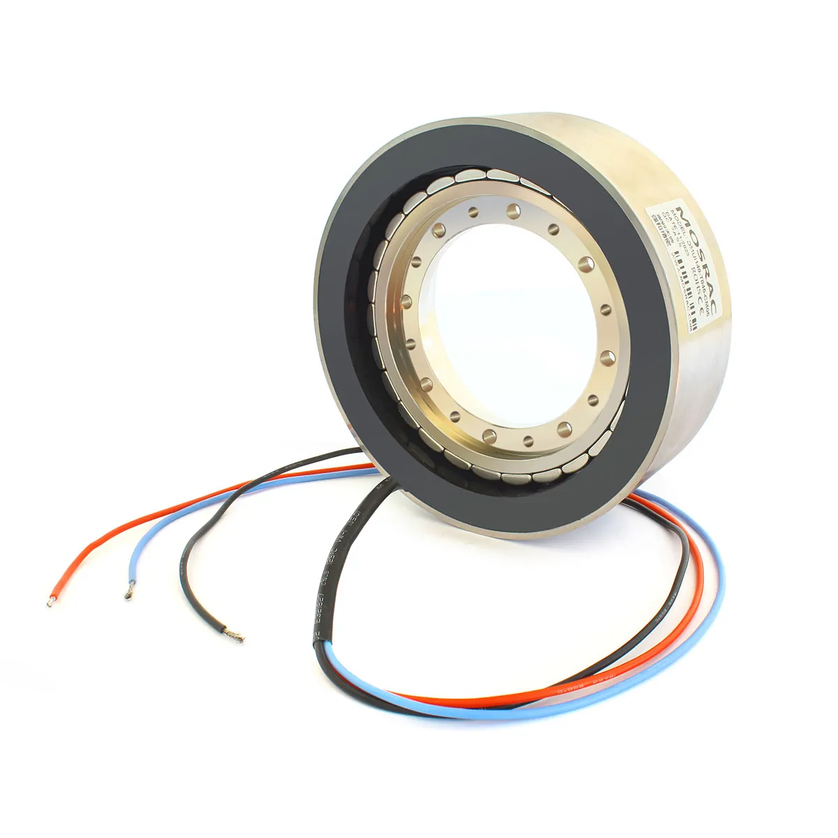
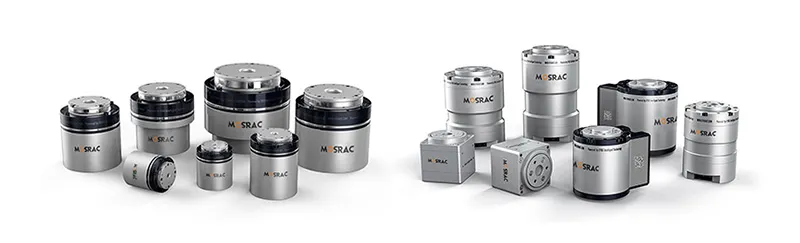
Mosrac Frameless Torque Motors
The motors manufactured by Mosrac benefit from electromagnetic flux optimization and finite element analysis in motor design, ensuring maximum torque quality improvement with minimal distortions. By choosing the right motor architecture and control system, you can effectively manage both cogging torque and torque ripple for superior operational precision.
Methods to Reduce Cogging in Electric Motors
Reducing cogging torque is critical for precision-driven applications such as robotics, medical devices, and industrial automation. Cogging torque arises primarily from the interaction between rotor permanent magnets and stator teeth, and can be minimized through both mechanical design improvements and advanced control strategies.
Design Modifications:
1. Skewing Stator Slots or Magnets
Skewing involves physically rotating the stator slots or the magnets on the rotor by a small angle along the axis of the motor. This distributes the cogging torque over a wider rotor angle, effectively reducing its peak value.
The formula to calculate approximate reduction:
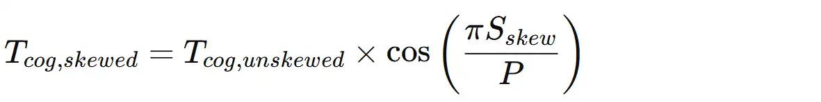
where, Tcog is the Cogging Torque, Sskew is the skewing angle (in electrical degrees), and Pis the number of poles
This technique is particularly effective in eliminating cogging torque and minimizing torque ripple in low-speed applications. The U50 Frameless Torque Motor Series leverages optimized magnetic design geometry to suppress cogging torque without compromising on torque density.
2. Using Fractional Slots per Pole
By utilizing fractional slot windings—where the number of stator slots per pole is a fraction rather than an integer—cogging torque can be reduced significantly. This disrupts the periodic alignment between rotor magnets and stator teeth.
Instead of a 12-slot/4-pole setup (3 slots per pole), using 15 slots/4 poles (3.75 slots per pole) can reduce cogging harmonics. This reduces slot harmonics, a known contributor to both cogging torque and crawling in induction motors.
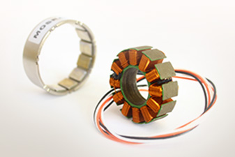
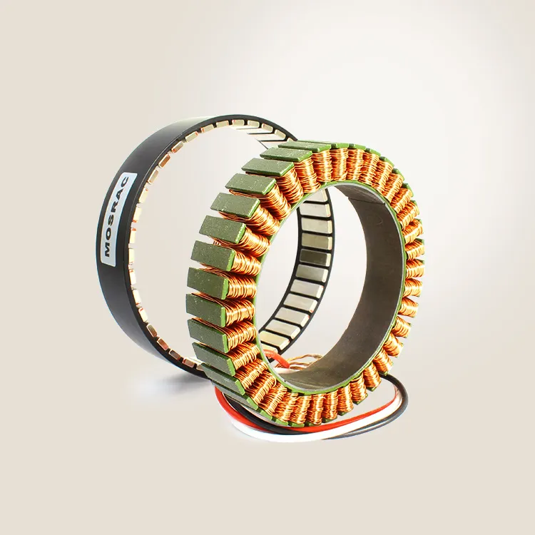
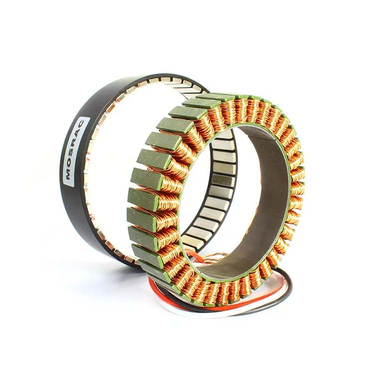
U38 Series 38MM Frameless Torque Motor
Several frameless motor variants (U38, U68 series) are wound using this principle, offering improved torque smoothness.
3. Optimizing Magnet Pole Arc or Width
Redesigning the rotor magnets by adjusting the pole arc (ratio between the arc covered by the magnet and the pitch between two magnets) can reduce the magnetic attraction with stator teeth. Shaped magnets (e.g., trapezoidal or sintered rare-earth magnets) are commonly used in this regard.
The ratio formula is stated as:

where, m is the magnet width (in mechanical degrees), and p is the pole pitch.
An ideal pole arc ratio (commonly ~0.7–0.8) minimizes torque ripple and cogging. Custom magnet shaping techniques are used in FE-Series Housed Motors, ensuring reduced cogging and stable low-speed torque.
Control Strategies:
1. Advanced Current Control Techniques
Field-Oriented Control (FOC) and Direct Torque Control (DTC) are modern control techniques that actively monitor and adjust current to counter torque irregularities. Combined with high-resolution feedback devices, this allows the motor to operate smoothly even at low RPMs.
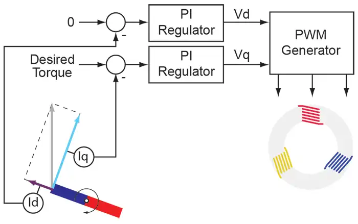
Advanced Current Control
FOC enables dynamic modulation of the stator current vector to compensate for disturbances. Algorithms can adjust for velocity ripple, and torque ripple, and reduce the effect of magnetic core saturation under dynamic loads in real time.
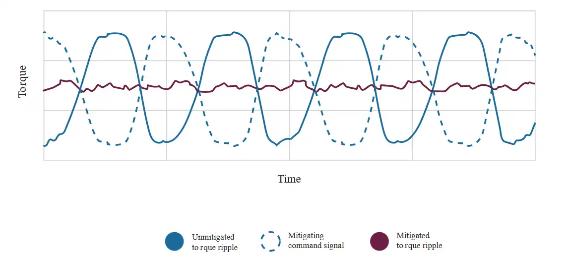
2. Implementing Cogging Torque Compensation Algorithms
These algorithms model and predict cogging torque at every rotor position and compensate by injecting counteracting current waveforms. When paired with digital servo drives, such algorithms can virtually eliminate the effects of cogging.
Below is the formula for the basic implementation:
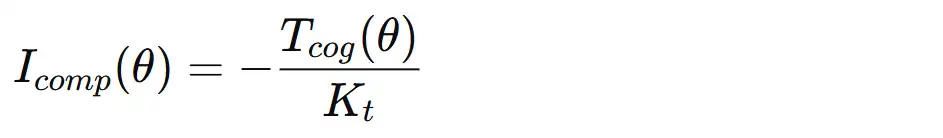
where, Icomp() is the compensating current, Tcog() is the cogging torque as a function of rotor position, and Kt is the torque constant of the motor.
Advanced controllers like those used in servo drive algorithms can store this torque map and apply real-time feedback, eliminating cogging torque at various speeds.
Recommended Reading: How to Choose the Right Torque Motor: 14 Essential Criteria
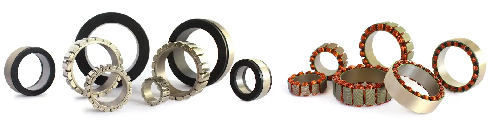
Slotless Permanent Magnet Motors: An Effective Solution
Slotless permanent magnet motors represent a cutting-edge solution to the challenge of cogging torque. By eliminating the stator slots—one of the primary sources of cogging—these motors provide extremely smooth and consistent torque output, making them ideal for ultra-precise applications.
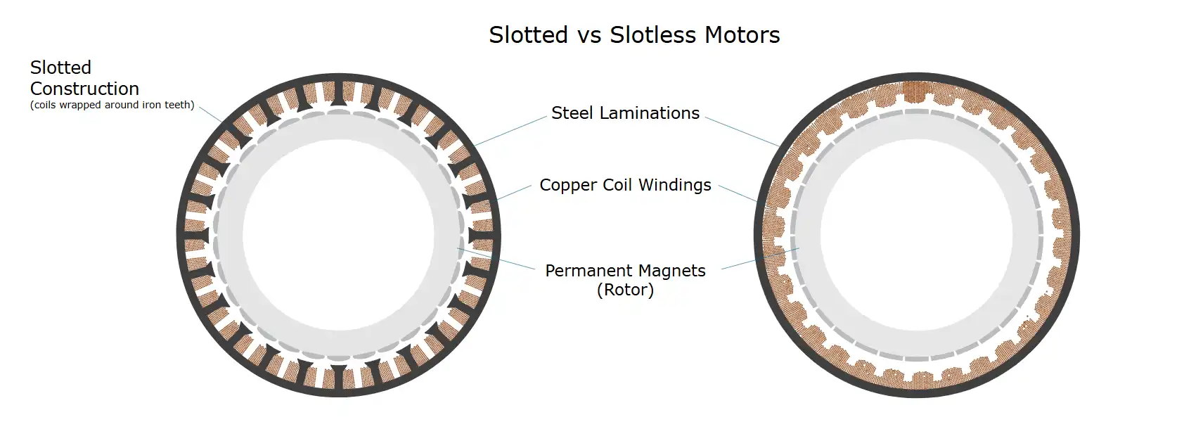
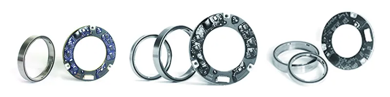
Slotted vs Slotless Motors
In conventional motors, cogging torque is produced by the interaction between permanent magnets on the rotor and the teeth of the slotted stator. Slotless motors, by contrast, feature a stator without slots. Instead, windings are embedded directly into a cylindrical, non-saturated core or supported by a self-supporting structure. This architecture completely removes magnetic locking and teeth locking effects.
Slotless motors typically feature:
-
▪︎ Air-gap winding or self-supporting coil structures.
-
▪︎ Laminated stator cores or wound-core configurations.
-
▪︎ Reduced inductance due to the absence of slots.
Below are the advantages in eliminating cogging torque:
1. Zero Cogging Torque
With no stator teeth for magnets to interact with, slotless motors inherently eliminate cogging torque. This allows for extremely low velocity ripple, critical in scanning systems and medical robotics.
2. Improved Torque Quality and Dynamic Response
The air-gap winding provides uniform torque generation, which greatly enhances torque quality improvement and minimizes torque ripple, especially at low speeds or during slow scanning operations.
3. Lower Acoustic Noise and Vibration
The absence of periodic torque pulsations leads to quieter operation, which is essential in laboratory automation and consumer medical devices.
4. Higher Speed Capability
Due to the reduced inductance and smoother electromagnetic flux distribution, slotless motors can achieve higher acceleration and top speeds with fast dynamic response.
Slotless motors are particularly valuable in applications that demand high smoothness, low noise, and high accuracy:
-
▪︎ Medical Equipment: Precision pumps, MRI-compatible devices, and surgical robots benefit from the low magnetic signature and cogging-free rotation.
-
▪︎ Semiconductor Manufacturing: Wafer inspection tools and lithography systems require sub-micron positioning accuracy, made possible by the zero-cogging architecture.
-
▪︎ Aerospace and Defense: Inertial navigation and gimbal stabilization systems use slotless motors for noise-free and jitter-free operation.
-
▪︎ Precision Optics & Cameras: High-end PTZ camera systems and telescopic controls demand smooth panning and focusing, which is achieved through slotless motor integration.
Slotless permanent magnet motors offer a fundamental design advantage by eliminating cogging at the source. These motors act as a powerful solution for industries that require the highest standard of motion smoothness, speed control, and energy efficiency.
Recommended Reading: Smart Housed Torque Motors: Integrating Sensors and Drives for Predictive Maintenance
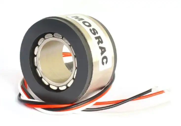
High-Precision Motors with Minimal Cogging
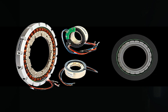
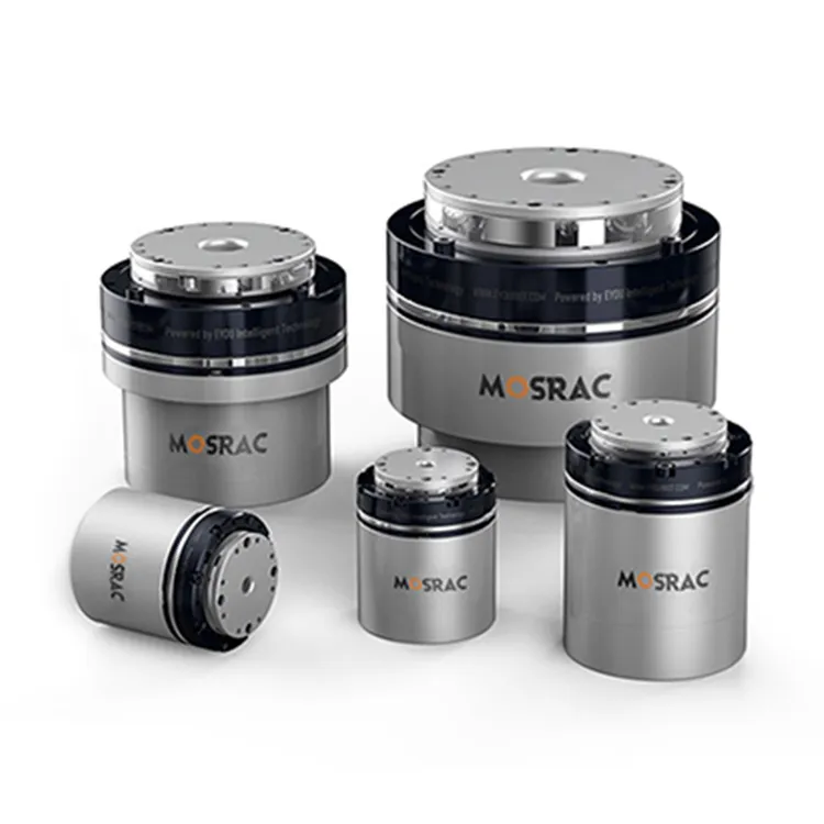
Mosrac offers a comprehensive range of servo torque motors tailored for direct drive applications.
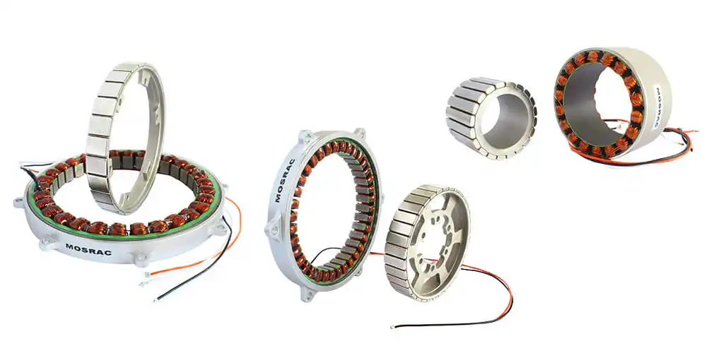
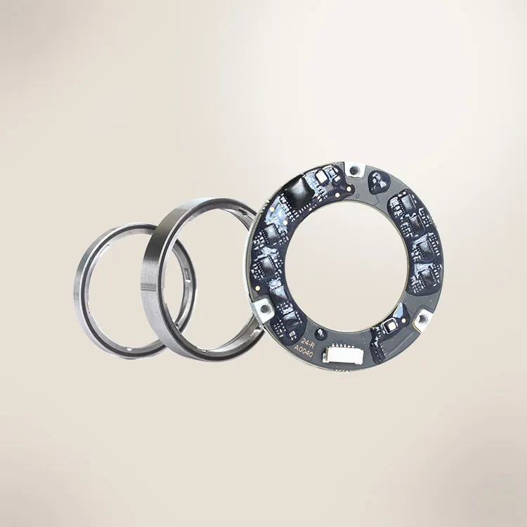
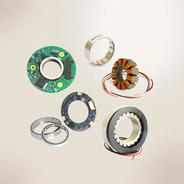
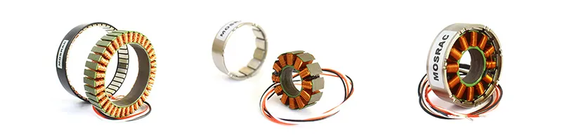
Newly launched Frameless DC Motors by Mosrac
Our product portfolio includes:
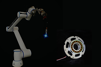
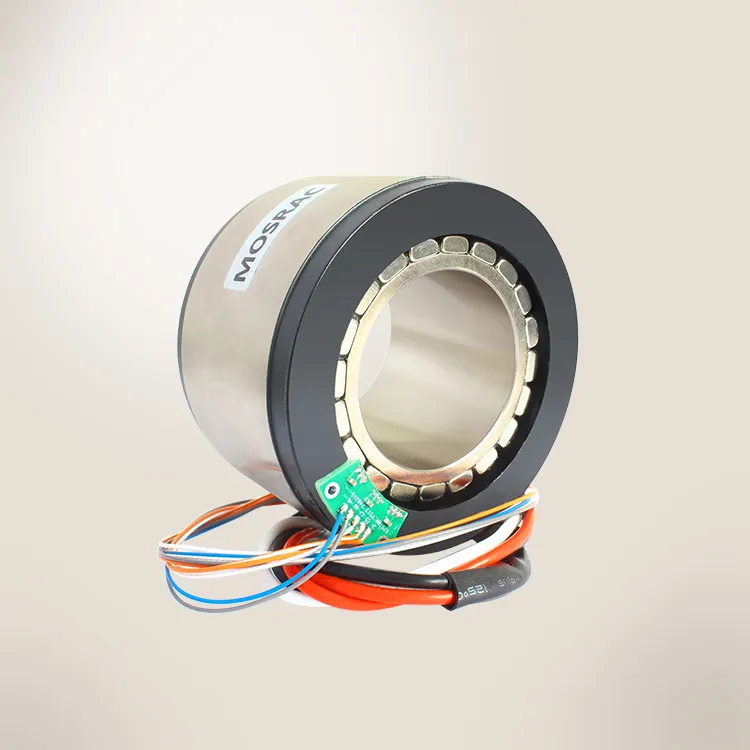
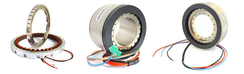
1. Frameless Inrunner Torque Motors (U-Series):
Compact, lightweight stator-rotor kits ideal for tight integration in robotic joints, rotary stages, and gimbal systems.
Example: U68 Frameless Motor
-
▪︎ Outer Diameter: 68 mm
-
▪︎ Rated Torque: 1.54 Nm
-
▪︎ Rated Speed: 3000 RPM
-
▪︎ Application: High-torque density in compact assemblies with minimal cogging.
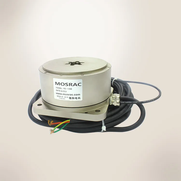
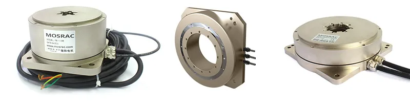
2. Housed Direct Drive Rotary Motors (FE, FI, FL Series):
Fully enclosed solutions with integrated cooling, feedback devices, and preassembled rotor-stator configuration for easy drop-in replacement.
Example: FE-140 Direct Drive Motor
-
▪︎ Rated Torque: 6 Nm
-
▪︎ Rated Speed: 300 RPM
-
▪︎ Precision Encoder: Magnetic Absolute Encoder
-
▪︎ Applications: Semiconductor equipment, machine tools, and high-resolution metrology.
Let’s go through their features and benefits:
1. Low Cogging Torque Design
-
▪︎ Utilizes fractional slot windings, skewed stator structures, and optimized magnet pole arc to eliminate magnetic locking effects.
-
▪︎ Enhanced torque quality through finite element analysis (FEA) and electromagnetic flux optimization.
2. High Dynamic Responsiveness
-
▪︎ Compatible with advanced servo drive algorithms for precise speed and torque control, even under rapidly changing load conditions.
3. Compact, High Torque Density
-
▪︎ Frameless models offer excellent torque-to-volume ratios, perfect for weight-sensitive environments like drones, exoskeletons, and aerospace systems.
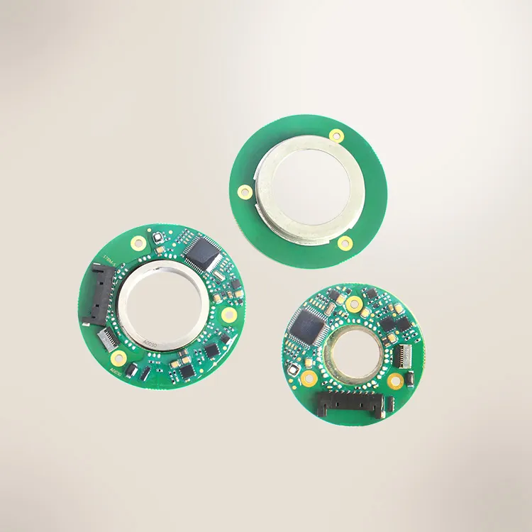
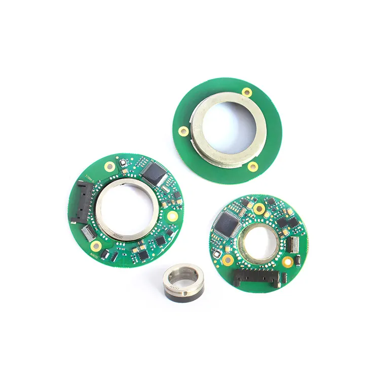
4. Seamless Feedback Integration
-
▪︎ Built-in magnetic absolute encoders ensure accurate position tracking, critical for motion control applications with minimal velocity ripple.
In addition to our standard models, Mosrac provides fully customizable motor designs tailored to your application's mechanical and electrical requirements:
-
▪︎ Modified stator and rotor dimensions for integration into non-standard housings
-
▪︎ Custom torque/speed curves for specific load profiles
-
▪︎ Application-specific winding and insulation classes
-
▪︎ Integration with proprietary encoders or resolver systems
-
▪︎ Enhanced cooling mechanisms for thermally demanding environments
Our engineering team collaborates directly with OEMs and automation specialists to create motors for unique challenges—ranging from magnetic core saturation control in high-field environments to slot harmonics reduction in ultra-silent drives.
Recommended Reading: Frameless Motor VS Brushless Motor: Which is Right for You?
Conclusion
Motor cogging, primarily caused by magnetic interactions between rotor magnets and stator slots, can severely impact the smoothness, accuracy, and efficiency of electric motors—especially in precision-critical industries.
We explored the nature of cogging torque, how it differs from torque ripple, and the engineering methods—such as skewing stator slots, fractional slot windings, magnet shaping techniques, and advanced control algorithms—that help in reducing it. Slotless permanent magnet motors stand out as a highly effective solution for eliminating cogging torque entirely.
Mosrac offers a range of high-precision frameless and housed torque motors, expertly engineered with these strategies in mind. Whether you need off-the-shelf or custom solutions, explore our products to experience cogging-free performance with superior torque quality—designed to meet the demands of next-generation applications.
Frequently Asked Questions
1. What causes induction motor cogging and how can it be reduced?
A. Induction motor cogging is often caused by poor stator and rotor slot alignment, and can be minimized through skewing stator slots and electromagnetic flux optimization.
2. How does permanent magnet motor cogging affect performance?
A. Permanent magnet motor cogging creates jerky motion at low speeds; anti-cogging strategies like fractional slot windings and magnet shaping improve torque quality and motion smoothness.
3. What are the best cogging torque reduction methods for precision motors?
A. Cogging torque reduction techniques include skewing stator slots, applying cogging compensation algorithms, and optimizing stator geometry using finite element analysis for torque quality improvement.
4. How do fractional slot windings and crawling in induction motors relate?
A. Fractional slot windings help suppress slot harmonics and reduce crawling in induction motors by breaking the magnetic symmetry that causes periodic torque pulsations.
5. How do cogging compensation algorithms enhance torque quality improvement?
A. Cogging compensation algorithms actively counteract torque disturbances, enabling smoother motion and torque quality improvement in precision applications like robotics and automation.
6. What role does electromagnetic flux optimization play in cogging torque reduction?
A. Electromagnetic flux optimization ensures uniform magnetic field distribution, reducing cogging torque and improving motor efficiency, especially in permanent magnet and direct drive motors.
Looking for a Custom Solution?
Tell us about your requirements, and our application engineers will help you find the right solution today!