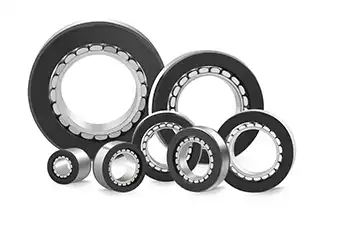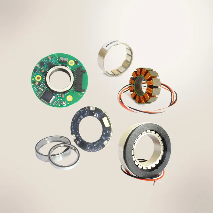

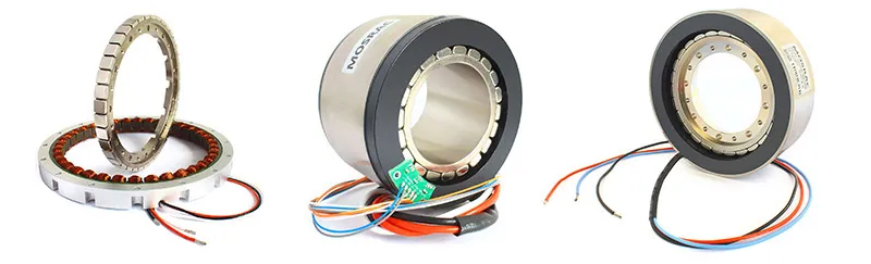

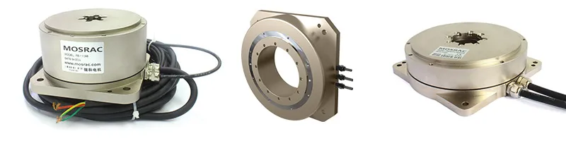
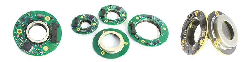
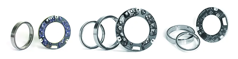


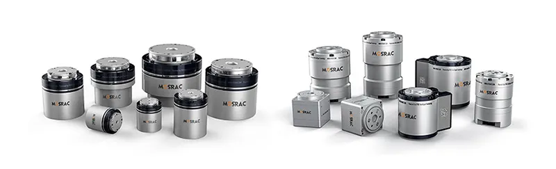


Mosrac - Ultra-Compact Frameless Motors
Key Takeaways
Definition: A frameless motor consists of a stator and rotor only; the machine supplies the housing, shaft, bearings, and feedback.
Architecture: Inrunners favour speed, low inertia, and heat dissipation, whereas outrunners deliver more torque for a given diameter in a flatter package.
Sizing: Selection is driven by continuous (RMS) and peak torque rather than power, followed by checks on envelope, winding and thermal path.
Integration: Reliable performance depends on a concentric air gap, a stiff housing, a suitable encoder and a planned heat path.
Applications: Humanoid and collaborative robots, dexterous hands, gimbals, machine tools and medical devices are the main users.
Mosrac offers over 100 standard inrunner and outrunner models from 12 to 200 mm OD, together with custom windings, fully custom designs and a 24-hour design-and-quote service.
Introduction
If you are designing a robot joint, a surgical tool or a precision rotary axis, a conventional housed servo motor often wastes the space you need most. Its housing, shaft, and bearings duplicate parts your mechanism already has. The frameless motor addresses this problem by supplying only the parts that produce torque and leaving the rest of the structure to the machine itself.
This guide explains what a frameless motor is, how frameless BLDC torque motors work, the difference between inrunner and outrunner designs, how to size and mount one, and which Mosrac frameless motor series fits each application — from the 12 mm U12 for robot fingers to the 200 mm U200 rated up to 50 Nm.
What is a Frameless Motor?
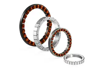
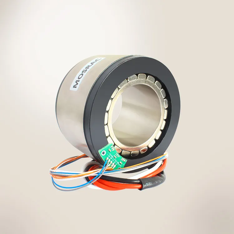
The frameless motor is a torque-producing core of an electric motor — the stator and rotor — delivered without a frame (housing), end bells, shaft, bearings, or encoder. The machine designer supplies those parts, so the motor becomes part of the mechanism instead of a separate component bolted onto it.
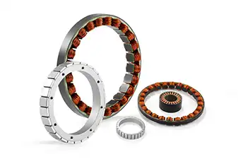
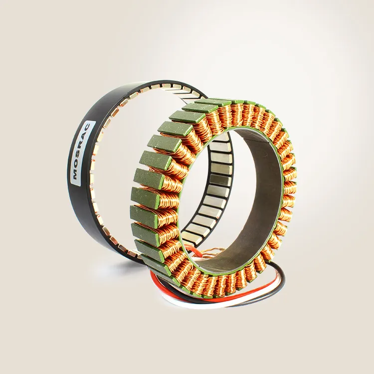
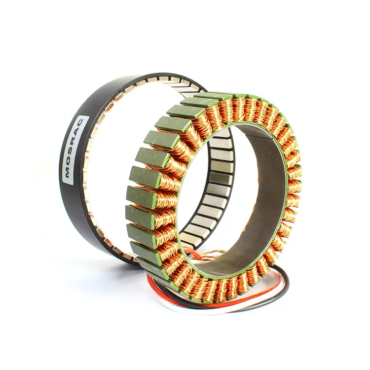
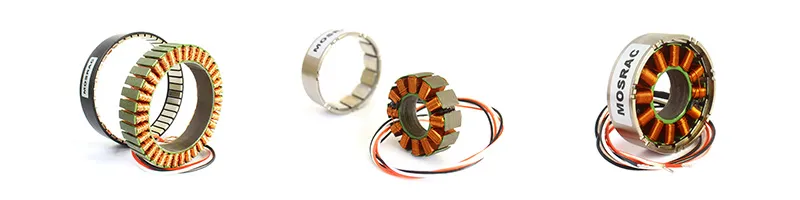
Frameless Motor Components: Rotor, Stator with Potting and Unpotted
In practice, "frameless motor" almost always means a frameless brushless DC (BLDC) motor, also called a frameless permanent magnet synchronous motor (PMSM). Because it is designed for high torque at low-to-moderate speed and drives the load directly, it is also called a frameless torque motor or direct-drive frameless motor. These terms describe the same product family.
What's in a Frameless Motor Kit?
The frameless motor kit comprises two matched components, each with a distinct role in producing torque:
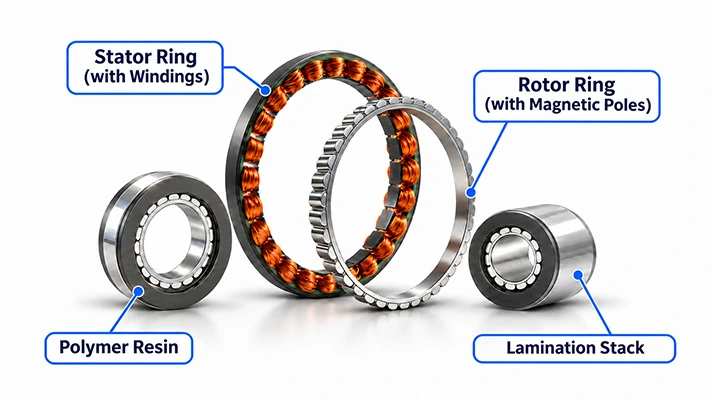
Stator — a stack of thin laminated electrical-steel sheets with copper windings in its slots. It is fixed to your housing and carries the phase leads, and usually Hall sensors and a thermistor.
Rotor — a steel hub with high-energy permanent magnets (typically NdFeB) bonded to it. It is fixed to your shaft or output flange and has a large hollow bore.
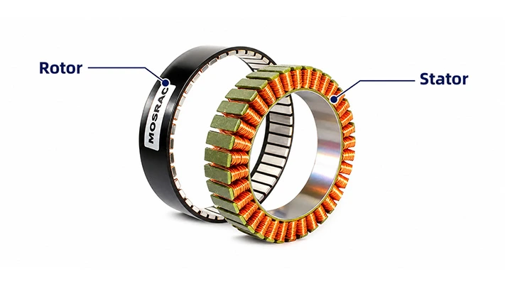
Exploded Outrunner Motor with Rotor and Stator
The two components are normally shipped as a matched pair, often with a non-magnetic spacer in the air gap that protects the magnets and maintains alignment until installation.
What Do You Add Yourself?
Because the kit omits every structural and feedback component, the machine designer is responsible for supplying the parts listed below. Each of them can therefore be selected for the application rather than accepted as a compromise built into a catalogue motor.
Housing / Stator Seat: Holds the stator concentric with the rotor and conducts heat away from the windings.
Shaft or Output Flange: Carries the rotor and transmits torque to the load.
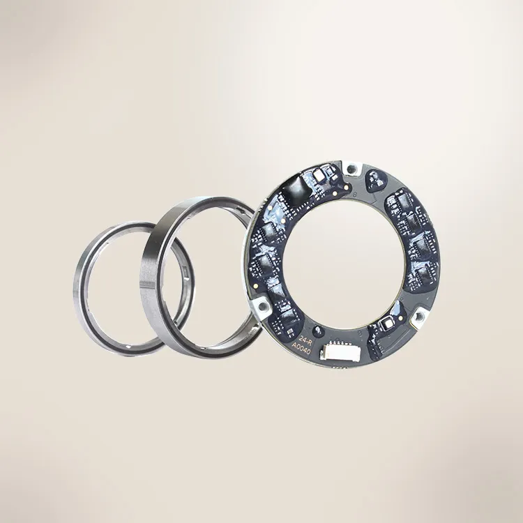
Bearings: Can be sized for the actual load, stiffness, and service life of the machine.
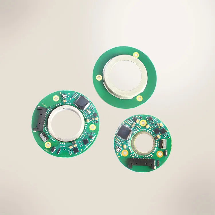
Feedback Device: An encoder or resolver provides position for commutation and closed-loop control.
Brake (Optional): Holds position when power is removed, which is common in robot joints.
Servo Drive: Commutates the windings and closes the current, velocity and position loops
The trade-off is straightforward: the designer accepts additional engineering work, and in return the motor fits the available geometry exactly instead of forcing the design around a standard housing.
Do Frameless Motors have Brushes?
The modern frameless motors do not have brushes, because they are brushless designs in which the servo drive commutates the windings electronically. This eliminates the brushes and mechanical commutator that would otherwise wear and generate debris inside a sealed mechanism. Brushed frameless DC motors are still produced, but they are now confined to a small number of legacy or low-cost applications, as discussed in a detailed brushless vs brushed motors comparison.
How Does a Frameless Motor Work?
The frameless motor operates on exactly the same principles as any brushless servo motor; the only difference lies in where its supporting components come from, not in how it produces torque.
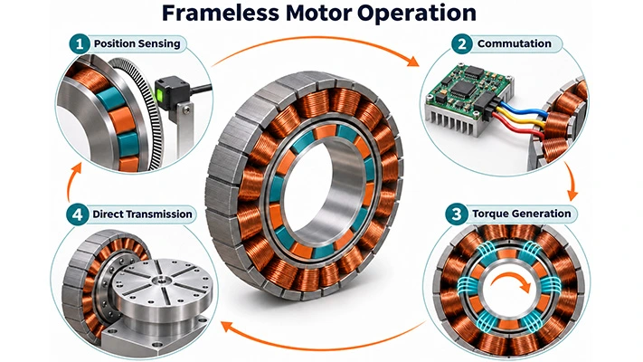
Frameless Motor Operation
Their operation can be described as a continuous four-stage cycle:
Position Sensing: Hall sensors or an encoder report the angular position of the rotor magnets to the servo drive.
Commutation: The drive switches current through the three stator phases, either in a trapezoidal sequence or as shaped sinusoidal currents under field-oriented control (FOC), which gives smoother torque.
Torque Generation: The rotating magnetic field created by the stator interacts with the rotor magnets across a narrow radial air gap.
Direct Transmission: Because the rotor is mounted on the load itself, torque reaches the load without passing through a gearbox, belt or coupling, so no backlash is introduced between motor and load.
The torque produced is proportional to phase current:
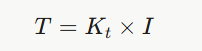
where T is torque (Nm), Kt is the torque constant (Nm/A), and I is phase current (A). In practice, two limits apply. Continuous torque is limited by heat, since winding losses rise with the square of current, whereas peak torque is limited by the current the drive can supply and by magnetic saturation of the steel. Both limits must be considered when sizing any frameless torque motor.
Why are Frameless Torque Motors Large in Diameter?
The torque a motor can produce rises with the square of its rotor diameter multiplied by its stack length, a relationship often called the D²L rule. Increasing diameter adds torque far more effectively than increasing length. This is why frameless torque motors are built as wide, pancake-style rings, enabling high-torque direct drive without requiring high-speed gearboxes.
The underlying design principles are covered in more depth in torque motors and torque motor design and control.
Frameless BLDC Motor Features that Matter
Several electromagnetic design choices determine how well a frameless BLDC motor performs in a direct-drive role:
Pole Count: The higher pole count increases torque at low speed and produces smoother motion. U-series motors, for example, are offered from 4 to 64 poles, as explained further in the guide to motor pole count.
Winding Type: Concentrated and distributed windings trade torque density against smoothness and achievable speed; the differences are set out in motor winding types.
Cogging Torque: The choice of slot and pole combination, together with magnet shaping, reduces the torque ripple that becomes noticeable at low speed, a topic covered in detail in motor cogging.
Hollow Bore: The large rotor bore allows cables, air lines, optical paths or a second shaft to pass through the centre of the axis, which simplifies routing in multi-axis robots.
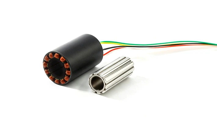
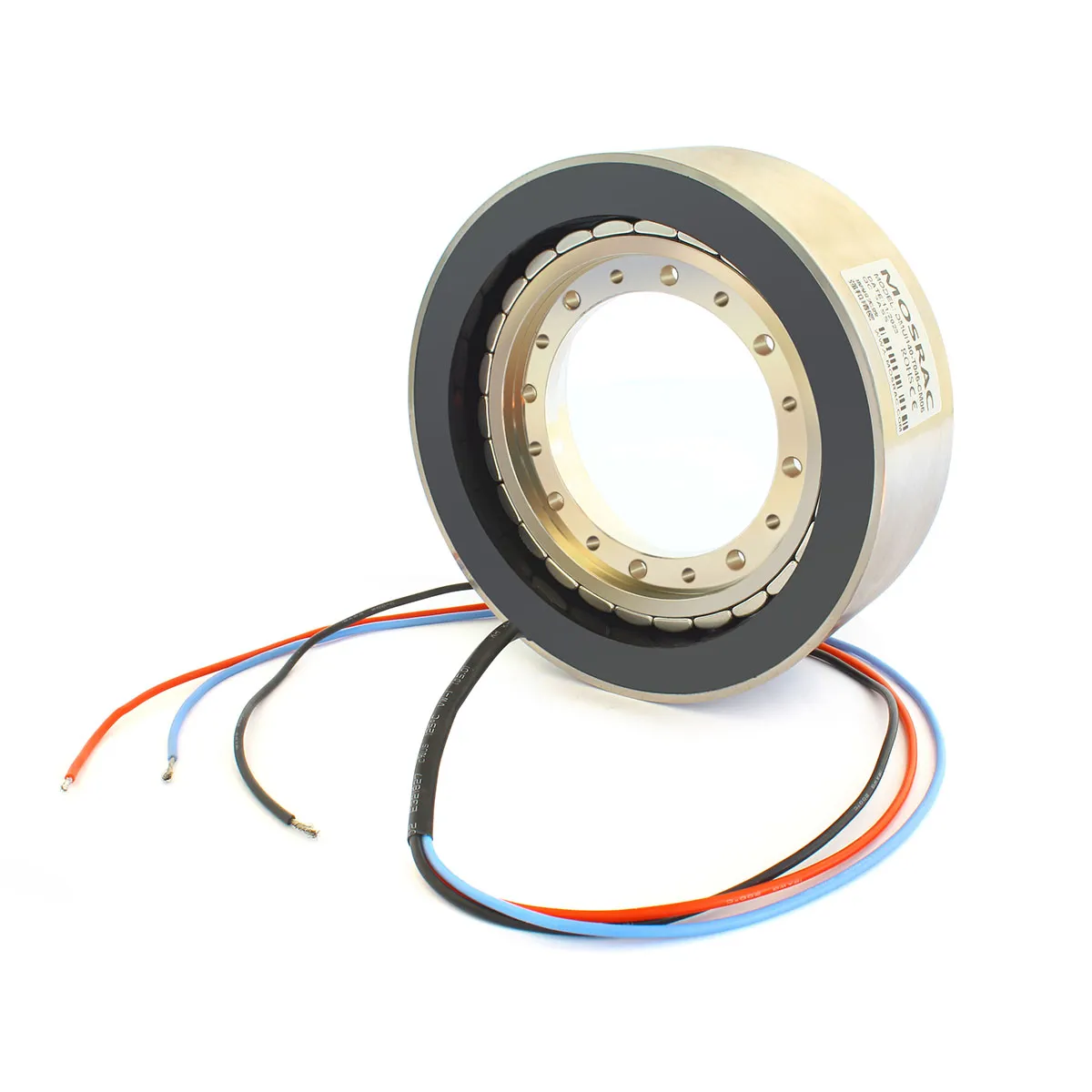
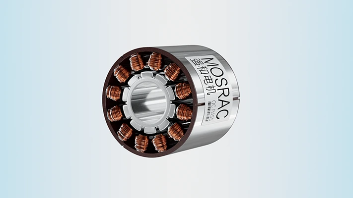
Mosrac U1934 Frameless BLDC Motor showing the Hollow Bore
Frameless Motor Architecture: Inrunner vs Outrunner
Every frameless motor follows one of two architectures, defined by whether the rotor sits inside or outside the stator. Because this single choice shapes torque, speed, inertia, heat dissipation and packaging, it is usually the first decision in a frameless motor design.
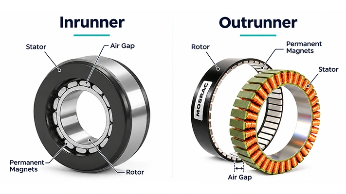
Inrunner vs Outrunner
Structural Differences between Inrunner and Outrunner Frameless Motors
The two architectures differ in where the magnets, windings, and mounting interfaces sit, as summarised below.
In an inrunner, the rotor sits inside the stator and is fixed to a shaft, while the windings occupy the outer ring and are pressed directly against the machine housing. In an outrunner, the arrangement is reversed: the stator is fixed to a central hub, and the rotor takes the form of an outer ring whose rotation drives the load.
Mosrac U1919 and U1925 Ultra-Compact Frameless Motors
The frameless inrunner motors at Mosrac span the full 12–200 mm OD range. The ultra-compact class from 12 to 19 mm OD is designed for robot fingers and grippers, while standard and large sizes from 25 to 200 mm OD serve robot joints and rotary tables. The frameless outrunner motors address flat, high-torque joints, and where no standard size fits the envelope, Mosrac builds custom OD, ID and stack lengths.
Key Performance Differences between Inrunner and Outrunner Frameless Motors
These structural differences translate directly into differences in dynamic and thermal performance.
The rotor of an inrunner is small in diameter; its inertia is low, which allows rapid acceleration and higher operating speeds. Its windings are also in direct contact with the housing, so heat leaves the motor along a short conductive path, which in turn supports higher continuous torque. The outrunner, by contrast, places its magnets at a larger radius, so it produces more torque for the same outside diameter and does so in a flatter package. The penalty is higher rotor inertia and windings that are enclosed by the rotating ring, which makes continuous torque more dependent on careful thermal design.
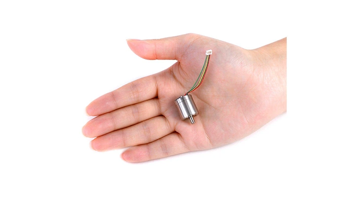
Permanent Magnet Synchronous Motor, including a 19 mm Ultra-Compact, Frameless Motor
Motor size also changes the performance picture. The ultra-compact frameless inrunner motors from 12 to 19 mm OD run at high speed and low torque, so they are frequently paired with a small gearhead, whereas larger diameters from 25 to 200 mm OD can deliver enough torque for direct drive without any reduction stage. Mosrac tunes windings for either high-speed or high-torque operation on both architectures, allowing performance to be matched to the requirements of a specific joint.
Choosing a Frameless Motor Architecture for Your Joint
The following guidelines, at the start, link typical joint requirements to the architecture that suits them best:
High Load, Low Speed and Limited Axial Space: Outrunner, as used in gimbals, quadruped legs and flat joints.
High Speed, Compact Size or a Demanding Thermal Duty: Inrunner, as used in robot joints, rotary tables and medical axes.
Severely Restricted Space: The ultra-compact inrunner, as used in dexterous fingers, grippers and handheld tools.
If the requirements fall between these cases, the application engineers at Mosrac recommend an architecture and size as part of a 24-hour design and quote.
Frameless Motor vs Other Motor Types
The frameless motor is less a distinct type of motor than a different way of supplying one, so the most useful comparisons are with the alternatives an engineer would otherwise specify for the same axis.
Frameless Motor vs Housed BLDC or Servo Motor
The table below compares a frameless motor with a conventional housed BLDC or servo motor, which is the most common alternative in automation and robotics.
Frameless Motor vs Housed Direct Drive Motor
The housed direct drive (DD) motor applies the same direct-drive principle as a frameless motor, but adds its own bearings, housing and encoder so that it can be bolted onto a machine like a standard motor.
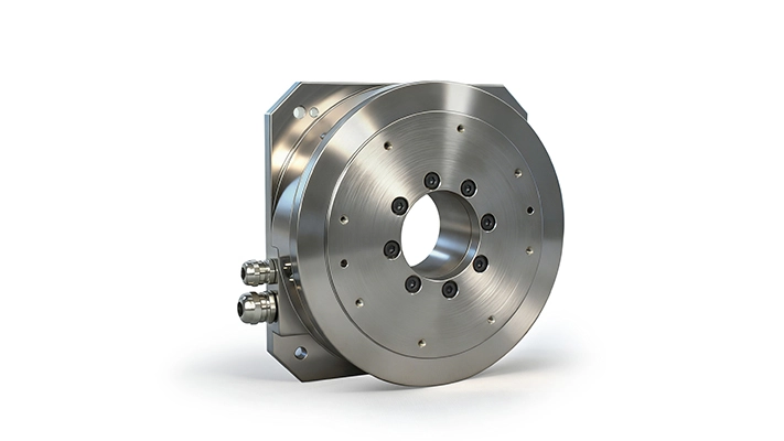
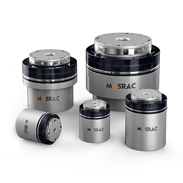
Mosrac - Housed Direct Drive Rotary Motor
The frameless motor is a better choice when size, weight or a through-bore is a hard constraint, whereas a housed DD motor suits designs that need direct-drive accuracy without the effort of engineering a bearing system. Because Mosrac manufactures both frameless motors and housed direct drive rotary motors, the decision can be based on integration effort alone. The principles behind housed designs are explained in what is a DD motor.
Frameless Motor vs Stepper and Induction Motors
Stepper and induction motors are occasionally considered for the same applications, although neither is well suited to a compact precision joint:
Stepper Motors: Inexpensive and simple to drive in open loop, but their torque falls away at speed, and they can lose steps under load.
Induction Motors: Rugged and economical to operate, but they offer limited positioning precision and require large frames for a given torque.
Is a Frameless Motor a Servo Motor?
The frameless motor becomes a servo motor once it is paired with a feedback device and a servo drive that closes the control loop. The term "frameless servo motor" therefore simply describes a servo motor before it is housed, with the shaft, bearings and frame supplied by the machine. The guide to servo motors covers servo control in more depth.
Frameless Motor Advantages and Limitations
Frameless motors offer the highest torque density and stiffness of any servo option, but those benefits come with greater responsibility for the mechanical design around the motor.
Advantages of Frameless Motors
Smaller, Lighter Axis: Eliminating the duplicate housing, shaft and bearings reduces both the mass and the envelope of the joint.
Zero Backlash and High Stiffness: Because the load is coupled directly to the rotor, there is no gear lash or belt compliance to degrade positioning accuracy.
Hollow Bore: Cables, air lines or optical paths can be routed through the centre of the axis.
Improved Heat Path: The stator sits in a housing designed by the machine builder, which can act as an effective heat sink.
Quieter Operation and Fewer Wear Parts: With no gear mesh and no brushes, both acoustic noise and maintenance are reduced.
Suitability for Harsh or Hygienic Environments: The motor can be sealed inside the machine for vacuum, washdown or subsea service.
Lower Cost in Volume: Manufacturers avoid paying for structural parts that the machine already contains.
Limitations and How to Manage Them
Each of the limitations below can be managed through design practice and supplier support.
Additional Design Work: Mosrac application engineers review the housing and bearing design.
Tolerances and Air Gap: Follow the concentricity values on the drawing supplied for each model.
Magnetic Attraction during Assembly: Use an insertion fixture or guide sleeve.
No Built-In Ingress Protection: The machine enclosure determines the IP rating.
Separate Feedback Device: Select the encoder early in the design process.
How to Select and Size a Frameless Motor?
The frameless motor should be sized on torque rather than power. Its continuous torque rating must exceed the RMS torque of the duty cycle, and its peak torque rating must cover the most demanding move, after which the envelope, winding and thermal path can be checked.
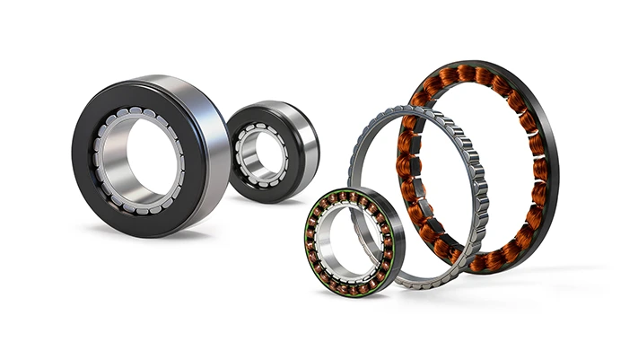
Potted and Unpotted Frameless Motor Stators
Step 1: Define the Load and Motion Profile
Sizing begins with a complete description of what the axis must do. This includes the load inertia, friction, gravity or offset loads and any external process forces, together with the target accelerations and the move and dwell times that make up one full cycle. Omitting a load at this stage, such as cable drag through a hollow joint, is one of the most common causes of an undersized motor.
Step 2: Calculate Continuous and Peak Torque
Peak torque is determined by the most demanding acceleration plus all static loads acting at that moment. Continuous torque, by contrast, is the root-mean-square (RMS) value of torque over the full cycle:
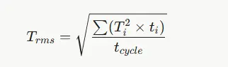
where Ti is the torque during segment i, ti is the duration of that segment, and tcycle is the total cycle time. The margin of 20–30% is typically added to both values to allow for modelling uncertainty and ageing.
Step 3: Match Envelope, Voltage and Winding
Once the torque requirement is known, the physical envelope and electrical supply narrow the choice further:
Envelope: Fixing the maximum OD, minimum bore and maximum length first determines whether the design falls into the ultra-compact or the standard size class.
Winding: The winding sets the torque constant and maximum speed for a given supply voltage. A winding with a higher Kt draws less current for the same torque but reaches its speed limit sooner, as explained in the motor constant.
Customisation: Mosrac provides custom windings on its standard frames at no additional charge, so the torque-speed curve can be matched to the supply voltage without a fully custom motor.
Step 4: Plan the Thermal Path
The rated continuous torque of a frameless motor assumes a specified heat sink. A small housing, a high ambient temperature or a sealed enclosure reduces the torque that can be sustained, whereas liquid cooling channels in the housing increase it. Because the thermal path frequently determines the final motor size, it should be modelled early rather than checked at the end of the design.
Step 5: Direct Drive or Frameless Motor plus Reducer?
Direct drive offers the highest stiffness and eliminates backlash entirely, but it is not always the lightest solution. In humanoid and collaborative robot joints, where torque per kilogram often matters more than absolute stiffness, a frameless motor combined with a harmonic or planetary reducer is common. For these designs, Mosrac also supplies harmonic and planetary joint modules that integrate a frameless motor, reducer and encoder in a single unit.
Standard, Modified or Custom Frameless Motor?
Frameless motors are available at three levels of customisation, each suited to a different stage or type of project.
Standard: Nothing changes, and a datasheet and STEP file are available, which makes this the right option when speed to prototype is the priority.
Modified: The custom winding is applied to a standard frame, which suits projects where the voltage or speed does not match a standard model.
Fully custom: Dimensions, magnets, sensors and leads are all designed to order, for applications whose envelope or performance requirement is unique.
Mosrac supports all three routes from prototype through to volume production, and returns an electromagnetic design and quote within 24 hours of receiving a specification. The broader considerations are discussed in custom motors.
What Drives Frameless Motor Cost?
The cost of a frameless motor depends on considerably more than its size. The principal drivers are as follows:
Diameter and Stack Length: These set the quantity of copper, electrical steel and magnet material in the motor.
Magnet Grade: High-temperature NdFeB grades cost more than standard grades.
Level of Customisation: Standard models cost the least, custom windings add relatively little, and fully custom designs add tooling and engineering effort.
Sensors and Leads: Hall sensors, thermistors and non-standard cable lengths each add cost.
Volume: Unit cost falls significantly between prototype and production quantities.
It is also worth considering total axis cost rather than motor cost alone, because a frameless motor removes the gearbox, coupling and duplicate bearings that a housed solution would require. The project-specific price can be obtained by requesting a quote.
Frameless Motor Mounting and Integration
Mounting a frameless motor requires keeping the stator and rotor concentric. The precision axis tolerances make installation easier than expected.
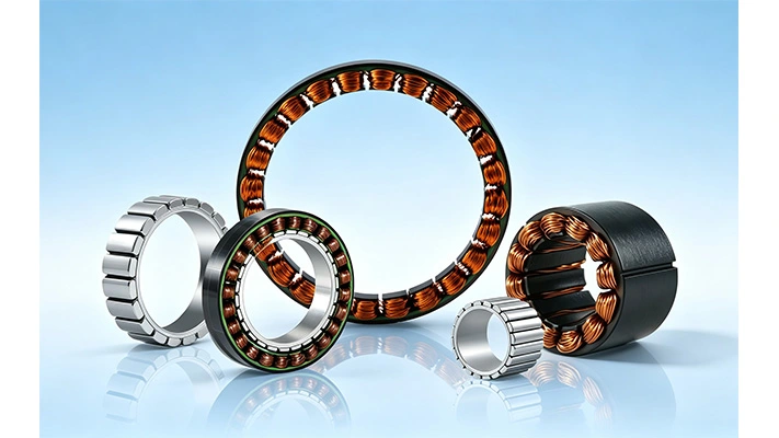
Mosrac Frameless Motors
Stator and Rotor Fixing Methods
Several fixing methods are in common use, and the right one depends on torque, vibration, thermal requirements and whether the assembly must be serviceable.
Bonding: The slip fit combined with a structural adhesive, which is simple and thermally effective for small and medium motors.
Clamping or Bolting: The clamp ring or flange compresses the stator, making this the preferred method for serviceable designs that must be disassembled.
Shrink or Press Fit: The interference fit, with the housing heated before insertion, suits high torque and high vibration and gives the best thermal contact.
Keyed or Pinned Rotor: The rotor hub is keyed or pinned to the shaft to withstand high peak torque and shock loading.
Step-by-Step Frameless Motor Assembly
The typical assembly sequence for a frameless inrunner proceeds as follows:
Prepare the Seats: Machine the stator bore and rotor seat to the tolerances on the supplier drawing, then deburr and clean both surfaces.
Fix the Stator: Install the stator in the housing using the chosen method, routing the leads out and providing strain relief.
Fix the Rotor: Attach the rotor to the shaft, taking care to keep metal swarf away from the exposed magnets.
Insert the Rotor: Because the magnetic attraction between rotor and stator is strong, use a guide sleeve, a non-magnetic shim or the bearings themselves to prevent the rotor from being pulled against one side of the stator.
Check the Air Gap: Confirm that the gap is even around the full circumference and that the rotor turns freely.
Set Commutation: Align the Hall-sensor or encoder offset with the drive, typically by using its auto-phasing routine.
Ground and Test: Earth the stator, then perform a low-current spin test before running the axis under load.
Air Gap, Concentricity and Rigidity
The uneven air gap creates unbalanced magnetic pull, increasing bearing loads, acoustic noise, and torque loss. Typical radial air gaps span 0.38 to 1.9 mm per side. Modern high-energy magnets tolerate minor misalignment, but a rigid housing and preloaded bearings remain essential to maintain gap stability under load.
Adding Feedback to a Frameless Motor
Hall sensors provide sufficient information for basic commutation, but precise position control requires an encoder. The absolute encoder retains position through power loss, and a hollow-shaft design preserves the motor's open bore for cabling. The slim inductive encoders at Mosrac are designed to sit alongside its frameless motors without closing the bore, and their operating principle is explained in the inductive encoder guide.
Cooling a Frameless Motor
Most frameless motors are cooled by conduction, with heat flowing from the stator windings into the metal housing and from there into the surrounding structure. Potting the stator in a thermally conductive compound improves this path by filling the voids between windings and laminations. Where an application demands high continuous torque, liquid cooling channels machined into the housing can raise the usable rating further.
Frameless Motor Applications
The table below maps the main application areas to the reasons frameless motors suit them and to the Mosrac series most often specified.
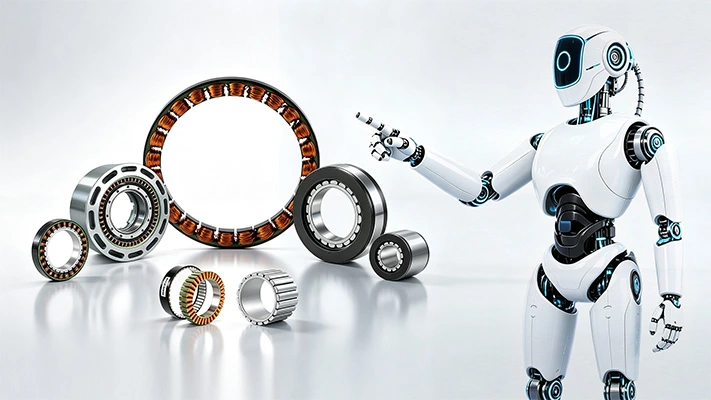
Frameless Motor Applications
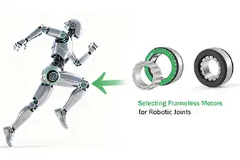
Robotics: Humanoids, Hands, Cobots and Legged Robots
Robotics accounts for the largest share of frameless motor use today. Humanoid joints, dexterous hands, grippers, cobots, quadrupeds and exoskeletons all require high torque from a small, light package, and many of them route cables through the centre of each joint. The ultra-compact motors from 12 to 19 mm OD fit inside finger joints, while motors from 60 to 130 mm OD are typical in hips, knees and shoulders. The frameless motors for linear joints at Mosrac extend the same approach to screw-driven actuators in humanoid arms and legs.
Precision Motion: Gimbals, Machine Tools and Semiconductor
EO/IR gimbals, rotary tables, indexers, wafer-handling robots, and packaging and printing machines all depend on smooth, backlash-free motion. In gimbals, where low height and jitter-free pointing are critical, flat outrunners are usually preferred. Rotary tables and machine tools, on the other hand, favour large inrunners from 130 to 200 mm OD, or housed direct drive motors where faster integration is required.
Medical, Aerospace and Defence
Surgical robots and handheld instruments need smooth, quiet motion within housings that can be sealed and sterilised, while aerospace and defence actuators operate under strict mass and envelope limits. Both sectors benefit from small frameless motors between 12 and 68 mm OD, as well as from custom U and UE designs built to the exact space available.
Mosrac Frameless Motor Range
Mosrac offers more than 100 standard frameless motors between 12 and 200 mm OD, each supplied with a datasheet and STEP file. Typical lead times for standard models are four to six weeks, and every model can be modified or fully customized.
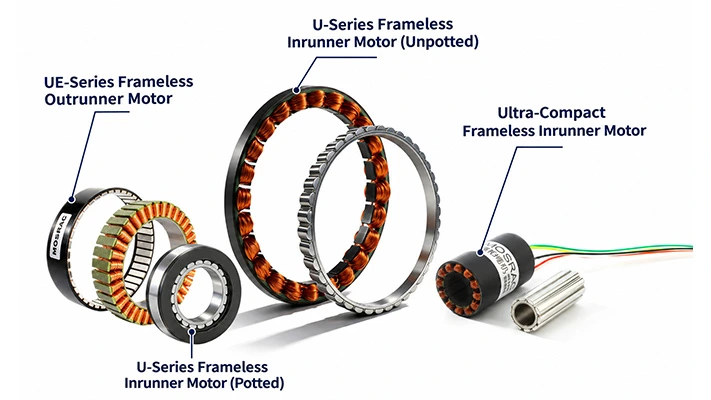
Mosrac Frameless Motors
Ultra-Compact Frameless Inrunner Motors, 12–19 mm
The ultra-compact range is designed for robot fingers, grippers and handheld surgical tools, where every millimeter of the envelope is accounted for. These motors operate at high speed and are commonly paired with a small gearhead to reach the torque a finger joint requires.
Browse: Ultra-Compact Frameless Motors
U-Series Frameless Inrunner Torque Motors, 25–200 mm
The U-series forms the core of the range for robot joints, medical axes and rotary tables, extending from compact 25 mm motors to 200 mm torque motors capable of direct drive.
Browse:U-Series Frameless Inrunner Motors
UE-Series Frameless Outrunner Motors, 15–109 mm
The UE-series provides flat, high-torque outrunner rings for dexterous hands, gimbals, humanoid limbs and quadruped legs, where axial space is limited but torque demand is high.
Browse:UE-Series Frameless Outrunner Motors
Frameless Motors for Linear Joints, 16–60 mm
This range comprises frameless rotary motors designed to drive roller or ball screws in compact linear actuators, which are used mainly in humanoid arms and legs.
Browse:Frameless Motors for Linear Joints
Standard, Modified or Fully Custom
Every series is available as a standard model, with a custom winding or as a fully custom design, following the options described in the selection section above. Further information is available on the Mosrac - Custom Solutions.
Getting Started with Your Frameless Motor Project
The frameless motors integrate directly into machinery, enabling remarkably compact, stiff, and quiet servo axes. Maximizing their performance requires making informed early design choices regarding architecture, torque sizing, air gap concentricity, encoders, and thermal management. Properly addressing these integration details significantly reduces axis size, weight, and overall cost while enhancing accuracy.
Engineers starting a new project can send Mosrac their torque, speed, voltage and envelope requirements and receive an electromagnetic design and sizing recommendation, with support from prototype through to volume production: Get a Free Quote in 24 Hours
Frequently Asked Questions
Q. What is a frameless motor?
A. The frameless motor is a brushless motor supplied as only a stator and rotor, without housing, shaft, bearings or encoder. The parts are built directly into a machine, so the motor drives the load with no gearbox or coupling.
Q. What is the difference between a frameless motor and a frameless torque motor?
A. There is none in practice. "Frameless torque motor" stresses that the motor is designed for high torque at low speed for direct drive, which describes most frameless motors.
Q. Is a frameless motor BLDC?
A. Yes. Modern frameless motors are brushless DC/PMSM motors with permanent-magnet rotors and electronic commutation. Brushed frameless DC motors exist but are rare today.
Q. What is the difference between an inrunner and an outrunner frameless motor?
A. The inrunner has the rotor inside the stator, giving better cooling and lower inertia. An outrunner has the rotor outside, giving more torque for the same diameter in a flatter package.
Q. Is a frameless motor a servo motor?
A. Yes, once it is paired with feedback and a servo drive. A frameless servo motor is simply a servo motor whose housing, shaft and bearings are supplied by the machine.
Q. What is a frameless motor kit?
A. The frameless motor kit is a matched stator and rotor pair, sometimes with Hall sensors and a thermistor fitted to the stator. Bearings, shaft, housing and encoder are supplied by the machine builder.
Q. How do you mount a frameless motor?
A. Fix the stator into the housing by bonding, clamping or shrink fit; fix the rotor to the shaft; then insert the rotor with a fixture so the air gap stays even. Use the concentricity values on the supplier drawing.
Q. Do frameless motors need cooling?
A. They need a heat path. The stator should sit in a metal housing that conducts heat away. For high continuous torque, liquid cooling channels in the housing can raise usable torque.
Q. What is the smallest frameless motor Mosrac makes?
A. The U12 series, at 12 mm outside diameter, with rated speeds up to 21,000 rpm. The UE1506 outrunner is 15 mm OD and weighs 6g.